Electromagnetic relay dynamic environmental test system

A technology of electromagnetic relay and mechanical environment, applied in the direction of circuit breaker testing, instruments, etc., can solve the problem that vibration condition control information and contact state monitoring information cannot be obtained at the same time, and achieve the effect of good control accuracy

Inactive Publication Date: 2010-06-02
HARBIN INST OF TECH
View PDF3 Cites 0 Cited by
  • Summary
  • Abstract
  • Description
  • Claims
  • Application Information

AI Technical Summary

Problems solved by technology

[0004] In order to solve the problem that vibration condition control information and contact state monitoring information cannot be obtained at the same time in the existing test process, the present invention proposes a mechanical environment test system for electromagnetic relays

Method used


Image

  • Electromagnetic relay dynamic environmental test system
  • Electromagnetic relay dynamic environmental test system
  • Electromagnetic relay dynamic environmental test system

Examples


specific Embodiment approach 1

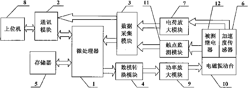
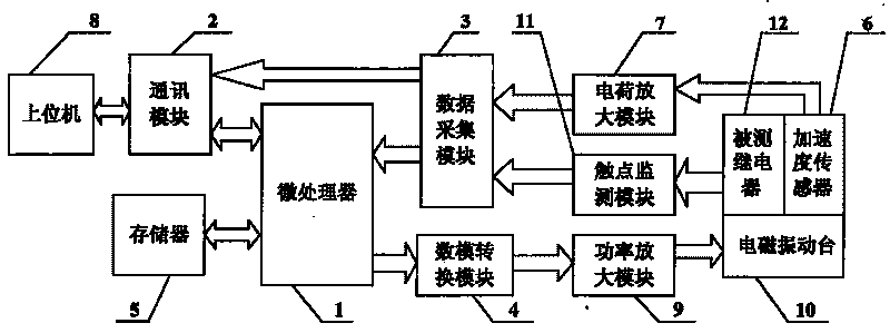
[0008] Embodiment 1: Combining figure 1 This embodiment is described. This embodiment consists of a microprocessor 1, a communication module 2, a data acquisition module 3, a digital-to-analog conversion module 4, a memory 5, an acceleration sensor 6, a charge amplification module 7, a host computer 8, a power amplification module 9, The electromagnetic vibration table 10 and the contact monitoring module 11 are composed; the microprocessor 1 is connected to the memory 5 through the address bus and the data bus, the data output end of the microprocessor 1 is connected to the data input end of the digital-to-analog conversion module 4, and the digital-to-analog conversion module The analog signal output end of 4 is connected to the analog signal input end of the power amplifying module 9, the output end of the power amplifying module 9 is connected to the driving input end of the electromagnetic vibration table 10, the measured relay 12 and the acceleration sensor 6 are arranged...

specific Embodiment approach 2

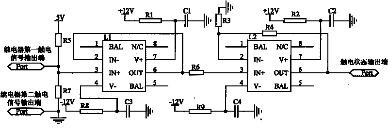
[0009] Specific implementation mode 2: Combining figure 2 Describing this embodiment, the difference between this embodiment and the specific embodiment is that the contact monitoring module 11 is composed of a first operational amplifier L1, a second operational amplifier L2, a first resistor R1 to a ninth resistor R9, and a first capacitor C1 to a third It consists of four capacitors C4; the first electric shock signal output end of the relay is connected to one end of the fifth resistor R5, one end of the seventh resistor R7 and the pin 3 of the first operational amplifier L1, the other end of the fifth resistor R5 is connected to the 5V power supply, and the first end of the relay is connected to the 5V power supply. The second electric shock signal output terminal is connected to the other end of the seventh resistor R7 and grounded, the pin 4 of the first operational amplifier L1 is connected to one end of the eighth resistor R8 and one end of the third capacitor C3, and...


PUM


Abstract

A mechanical environment testing system of an electromagnetic relay relates to the measuring field of the electromagnetic relay, solving the problem that the control information of vibration conditions and the monitoring information of contact states cannot be obtained simultaneously in existing testing processes. The system adds a contact monitoring module and the input end of the contact monitoring module is connected to a contact of a relay to be tested. The output end of the contact monitoring module is connected to the input end of a data collection module. The output end of the data collection module is connected to the input end of a microprocessor and the input end of a communication module. The microprocessor is connected with the communication module in series. The communicationmodule is connected with a USB port of an upper computer. The system combines the microprocessor and a real-time system to put up a closed-loop system and control an electromagnetic vibration table soas to achieve high control precision, truly simulate the working environment, exactly determine the failure mode of elements and mechanical weak links and further provide necessary material for vibration protection. The system realizes simultaneous working of the vibration test and the contact monitoring so as to more accurately record the mechanical weak links of the tested electric appliances.

Description

technical field [0001] The invention relates to the field of relay measurement. Background technique [0002] Electromagnetic relay is an automatic moving electrical appliance whose electrical output circuit is turned on (conducted) or broken (blocked, turned off) when the input physical quantity (electricity or non-electricity) reaches a specified value. , power system protection devices, various remote control and communication devices have a wide range of applications, is one of the basic electrical components in modern automatic control systems. [0003] Small sealed electromagnetic relays are widely used in high-end fields such as aerospace and national defense due to their irreplaceable advantages such as high switching power, high sensitivity, high conversion depth and strong environmental resistance. The switching function of the electromagnetic relay is generally realized by the two mechanical systems, the armature system and the contact system. Under the external ...

Claims


Application Information

Patent Timeline
Patent Type & Authority Patents(China)
IPC IPC(8): G01R31/327G01M7/00
Inventor 任万滨陈英华肖唐杰翟国富
Owner HARBIN INST OF TECH
Why Eureka
Try Eureka