Improved inrush current limiter device and power factor control circuit having the same

A surge current, limiter technology, applied in emergency protection circuit devices, circuit devices, control/regulation systems, etc. for limiting overcurrent/overvoltage, and can solve problems such as falling off, easy damage, and sudden work.

Inactive Publication Date: 2008-09-10
KONINK PHILIPS ELECTRONICS NV
View PDF0 Cites 9 Cited by
  • Summary
  • Abstract
  • Description
  • Claims
  • Application Information

AI Technical Summary

Problems solved by technology

This leads to a new problem: a large inrush turn-off current when the electrical power is initially applied
[0006] Some very complex circuits and drivers have been designed to handle this switching, but they can still fail when repeatedly turned on and off
Another drawback is that the circuits used to control the IGBTs are very complex and prone to damage
[0007] Moreover, power factor control circuits known in the prior art operate suddenly and drop out during the start-up cycle of the load due to the lack of synchronization between the load and the upstream configured buffer

Method used


Image

  • Improved inrush current limiter device and power factor control circuit having the same
  • Improved inrush current limiter device and power factor control circuit having the same
  • Improved inrush current limiter device and power factor control circuit having the same

Examples


Embodiment Construction

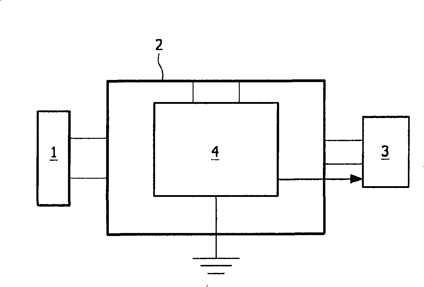
[0027] figure 1 The design of the invention is shown schematically, where the main power source 1 or the common ac power source is connected to the PFC circuit 2 via leads. The PFC circuit 2 is connected to a load 3, which may be any load, such as a lamp. The PFC circuit further comprises an inrush current limiter device 4 , which is grounded at one end and which takes information from the load 3 , which is represented by an arrow pointing away from the inrush current limiter device 4 towards the load 3 . figure 2 The inrush current limiter 4 is described in more detail in .

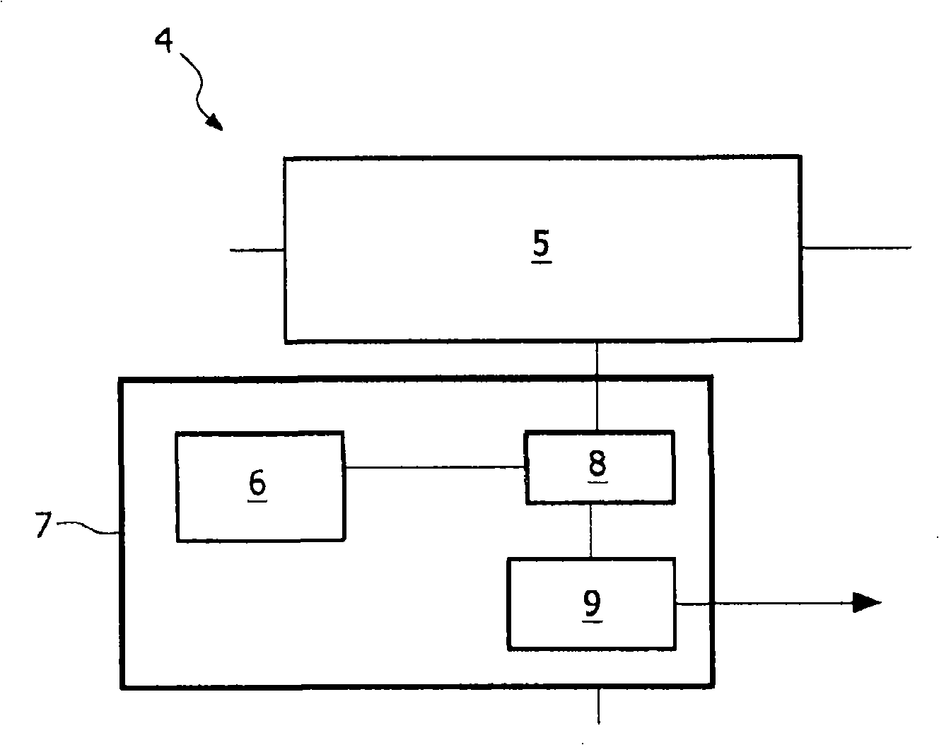
[0028] figure 2 The inrush current limiter device 4 of the present invention is schematically shown. The inrush current limiter device 4 comprises an IGBT-based limiter unit 5 having an unrestricted conduction path and a restricted conduction path (not shown in detail), which are alternately coupled via corresponding switches. The IGBT based limiting unit is powered by the IGBT gate supply 6 . The...


PUM


Abstract

The present invention relates to an inrush current limiter device (4) for limiting inrushing current to a connectable load (3) comprising: at least one switchable IGBT-based limiter unit (5) for selectively limiting the inrushing current, having at least one current limiting conductor element for a limited leading of current and at least an IGBT-based switch (Q2), whereby the IGBT-based switch (Q2) is used as well as a controlled current limiter and as a by-pass element, and at least one control device (7) for controlling the IGBT-based switch (Q2), whereby the control device (7) comprises at least one IGBT-based switch supply (6) and means for realizing (8) a smooth flank of an output signal at the selected conductor element.

Description

technical field [0001] The invention relates to an inrush current limiter device for limiting inrush currents directed to a connectable load, comprising at least one switchable IGBT (Insulated Gate Bipolar Transistor) based limiter unit for selective Ground limiting inrush current, which has at least one current-limiting conductor element for limited conduction current, and at least one IGBT-based switch, wherein the IGBT (Insulated Gate Bipolar Transistor)-based switch (Q2) Used as a controlled current limiter and bypass element, and at least one control device for controlling an IGBT-based switch, wherein the control device includes at least one IGBT-based switching power supply and for implementing an output signal at a selected conductor element Device with smooth sides. [0002] The invention further relates to a power factor control circuit connectable to and / or between a main fed and a load, comprising: an AC / DC converter with a capacitive buffer unit, and inrush curre...

Claims


Application Information

Patent Timeline
Patent Type & Authority Applications(China)
IPC IPC(8): G05F1/569H02M1/42H02H9/00
CPCG05F1/70H02H9/001H02M1/42Y02B70/10
Inventor W·施纳G·格罗伊尔M·M·A·布罗伊克斯
Owner KONINK PHILIPS ELECTRONICS NV
Why Eureka
Try Eureka