Ball-skin hole-drilling machine
A technology of cone hole and ball skin, which is applied in the field of ball skin cone hole machine, can solve the problems of high labor intensity, high manufacturing cost, and low work efficiency, and achieve the effect of reducing labor intensity, reducing production cost and improving work efficiency
- Summary
- Abstract
- Description
- Claims
- Application Information
AI Technical Summary
Problems solved by technology
Method used
Image


Examples
Embodiment 1
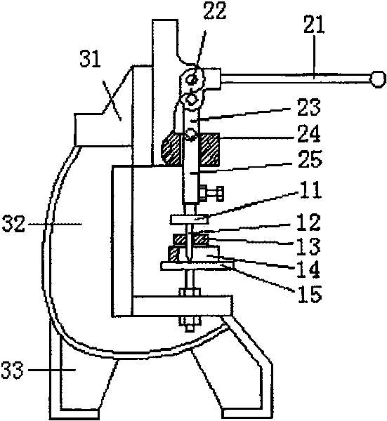
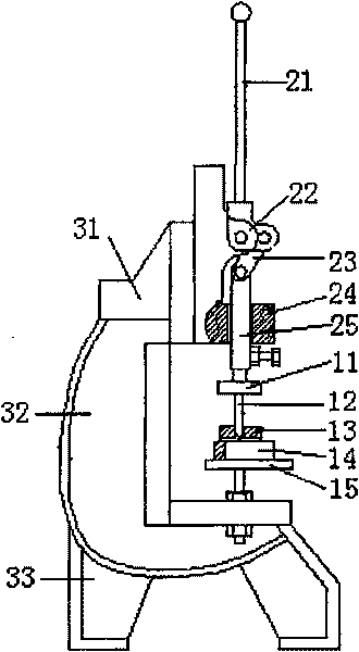
[0021] Embodiment one, such as figure 1 , 2 , 3 shown. The taper hole device of the present embodiment is mainly composed of a steel needle fixing plate 11, a steel needle 12, a needle withdrawal plate 13, a ball skin positioning plate 14, and a working platform 15. The steel needle fixing plate of the taper hole device is facing downwards, and the steel needles are installed side by side, and pass through the needle withdrawing plate, and the ball skin positioning plate is between the needle withdrawing plate and the working platform. Its pressurizing device mainly is made up of pressure rod 21, rotating shaft 22, connecting rod 23, guide sleeve 24, ejector rod 25. The pressure rod is connected with the connecting rod through the rotating shaft, the ejector rod is located in the guide sleeve, one end of the ejector rod is connected with the connecting rod, and the other end is connected above the steel needle fixing plate. Its fixing device is made up of fixing shoulder 31...
Embodiment 2
[0022] Embodiment two, such as Figure 4 , 5 As shown, the taper hole device of the present embodiment is mainly composed of steel needle fixing plate A11, steel needle A12, needle withdrawal plate A13, ball skin positioning plate A14, workbench A15 (also provided with a right angle wall). The installation method of each component of the tapered hole device is the same as that of the first embodiment. The pressurizing device of this embodiment is mainly composed of guide rod A21, return spring A22, guide rod connecting plate A23, vertical tie rod A24, horizontal tie plate A25, multi-section tie rod A26, and pressure bar A27. The lower end of the needle fixing plate is connected to the horizontal plate, the upper end of the multi-section tie rod is connected to the horizontal plate through a nut, and the lower end is connected to the pressure rod; the guide rod vertically passes through the steel needle positioning plate, and is connected to the workbench through the nut. The...
PUM
 Abstract
Description
Claims
Application Information
 - R&D
- Intellectual Property
- Life Sciences
- Materials
- Tech Scout
- Unparalleled Data Quality
- Higher Quality Content
- 60% Fewer Hallucinations
Browse by: Latest US Patents, China's latest patents, Technical Efficacy Thesaurus, Application Domain, Technology Topic, Popular Technical Reports.
© 2025 PatSnap. All rights reserved.Legal|Privacy policy|Modern Slavery Act Transparency Statement|Sitemap|About US| Contact US: help@patsnap.com