Lift traction device

An elevator traction and traction belt technology is applied in the field of traction devices for lifting articles, and can solve problems such as mutual interference of traction belts, overlapping of multiple traction belts, mutual interference, etc.

Active Publication Date: 2008-09-17
NINGBO HONGDA ELEVATOR
View PDF0 Cites 20 Cited by
  • Summary
  • Abstract
  • Description
  • Claims
  • Application Information

AI Technical Summary

Problems solved by technology

①For the former, the traction belt on the traction sheave and the transition wheel may cause axial serial movement due to processing and installation deviations, and in severe cases, it may even cause multiple traction belts to overlap or interfere with each other
However, when the traction belt passes through the car and the transition wheel of the balance counterweight, since the back of the traction belt is a smooth plane, it may move axially on the transition wheel, causing mutual interference or even overlapping of the traction belt.

Method used


Image

  • Lift traction device
  • Lift traction device
  • Lift traction device

Examples


Embodiment Construction

[0013] The present invention will be described in further detail below in conjunction with the accompanying drawings and specific embodiments.

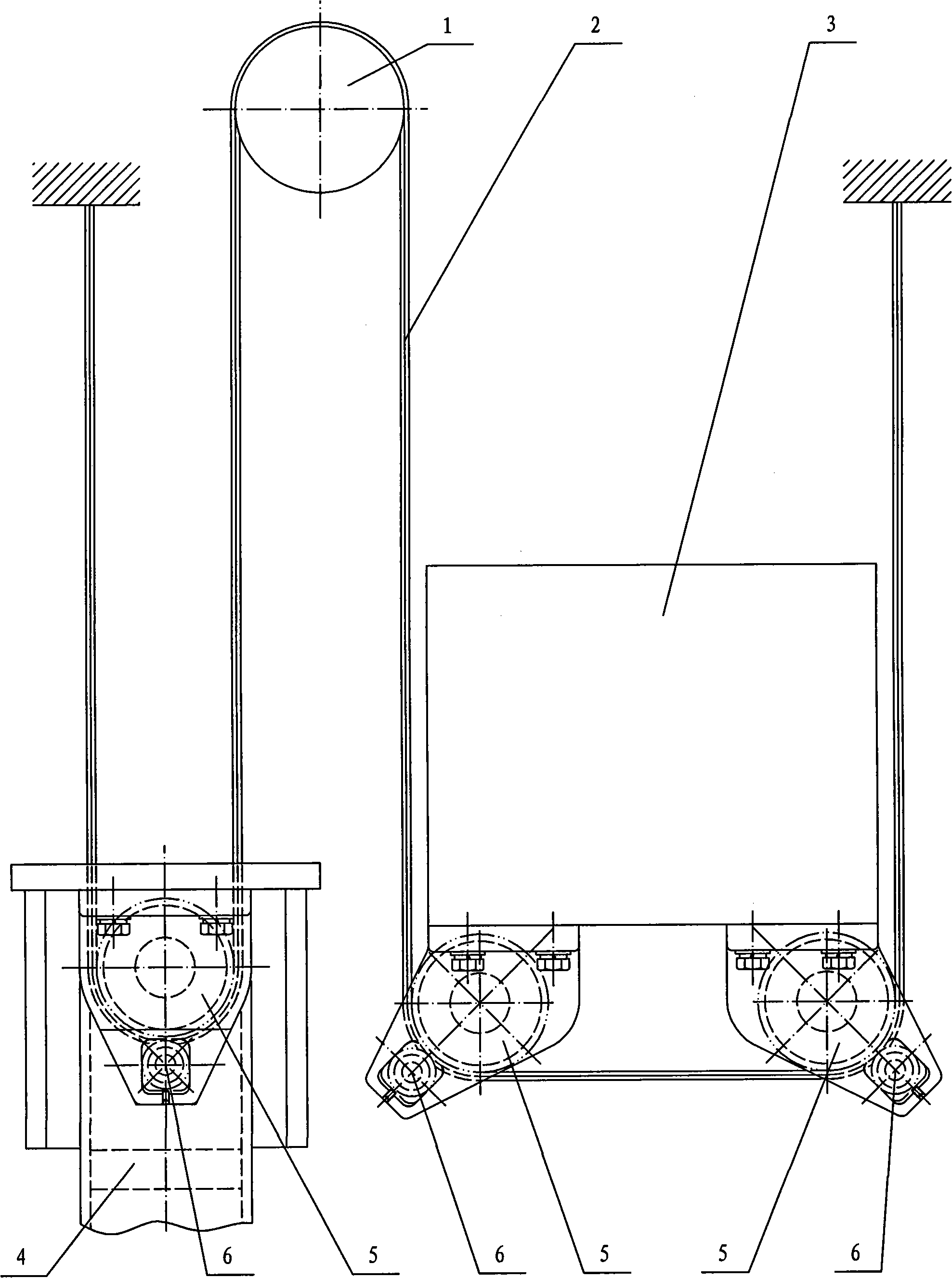
[0014] Depend on figure 1 It can be seen from the schematic structural diagram of the elevator traction device of the present invention that the elevator traction device comprises a traction machine 1 with a traction sheave 23, a traction belt 2 with protrusions 7 along the length direction, a car 3, Balance counterweight 4 and several transition wheels 5. The traction belt 2 is slip-fitted on the balance counterweight transition wheel 5, traction sheave 23, and car transition wheels 5. The two ends of the traction belt 2 are respectively fixed. In other words, one end of the traction belt 2 is fixed, and the other end passes through the balance counterweight transition wheel 5 , the traction sheave 23 on the traction machine 1 , and the car transition wheel 5 in sequence and then is fixed. Since the surface of the traction wheel 23...


PUM


Abstract

The invention discloses an elevator dray device, comprising a dray machine (1), a dray belt (2) with a convex (7) along length direction, an elevator car (3), a balanced counterweight block (4), and a plurality of transition wheels (5). The invention is characterized in that the dray belt (2) is slidingly matched with the transition wheels (5) of the balanced counterweitht block, a dray wheel (23) and the transition wheels (5) of the elevator car; both ends of the dray belt (2) are fixed; the surface of the dray wheel (23) is provided with a groove (8) matched with the convex (7) of the dray belt (2); a rectification small wheel (6) is positioned on one side of each transition wheel (5); the dray belt (2) is positioned between the transition wheels (5) and the rectification small wheels (6); the surface of each rectification small wheel (6) are provided with a groove (8) matched with the convex (7) of the dray belt (2). As a result, the elevator dray device has the advantages of avoiding the axial motion of the dray belt on the transition wheels and reducing manufacturing cost of the elevator dray machine without increasing the diameter of the dray wheel.

Description

technical field [0001] The invention relates to a traction device for lifting articles, in particular to a traction device used in an elevator to drive the car to move up and down. Background technique [0002] The current elevator traction device that drives the elevator car to move up and down is that the wire rope is suspended in the rope groove of the traction sheave, and the radius of curvature of the wire rope is the same as the radius of the traction sheave. In order to reduce the fatigue damage of the steel wire rope in the repeated bending state for a long time, according to GB7588-2003 "Safety Code for Elevator Manufacturing and Installation", the diameter of the steel wire rope must be ≥ 8mm, and the diameter ratio of the traction sheave to the steel wire rope must be ≥ 40. A large diameter of the traction sheave requires a large torque to move the car up and down, thereby significantly increasing the manufacturing cost of the traction machine. At the same time, ...

Claims


Application Information

Patent Timeline
Patent Type & Authority Applications(China)
IPC IPC(8): B66B11/04B66B11/08
Inventor 潘式正
Owner NINGBO HONGDA ELEVATOR
Why Eureka
Try Eureka