Planarity detection device and method

A technology of flatness detection and light receiving unit, which is applied in the direction of measuring devices, optical devices, instruments, etc., can solve the problems of detection accuracy decline, scratches on the surface of the workpiece to be measured, and affect the surface quality of the workpiece, etc., to achieve detection accuracy Easier, improved detection accuracy, and reduced labor fatigue

Inactive Publication Date: 2008-09-17
HONG FU JIN PRECISION IND (SHENZHEN) CO LTD +1
View PDF0 Cites 20 Cited by
  • Summary
  • Abstract
  • Description
  • Claims
  • Application Information

AI Technical Summary

Problems solved by technology

In this way, the detection accuracy of the platform and the feeler gauge will inevitably decrease after long-term use; and, the collision and friction between the surface to be tested of the workpiece and the platform and the feeler gauge during detection may also leave scratches on the surface of the workpiece to be tested, As a result, the surface quality of the workpiece is affected. If the workpiece has high requirements on the surface quality, this measurement method cannot meet the measurement requirements.

Method used


Image

  • Planarity detection device and method
  • Planarity detection device and method
  • Planarity detection device and method

Examples


Embodiment Construction

[0012] The flatness detection device and method will be further described in detail below with reference to the drawings and embodiments.

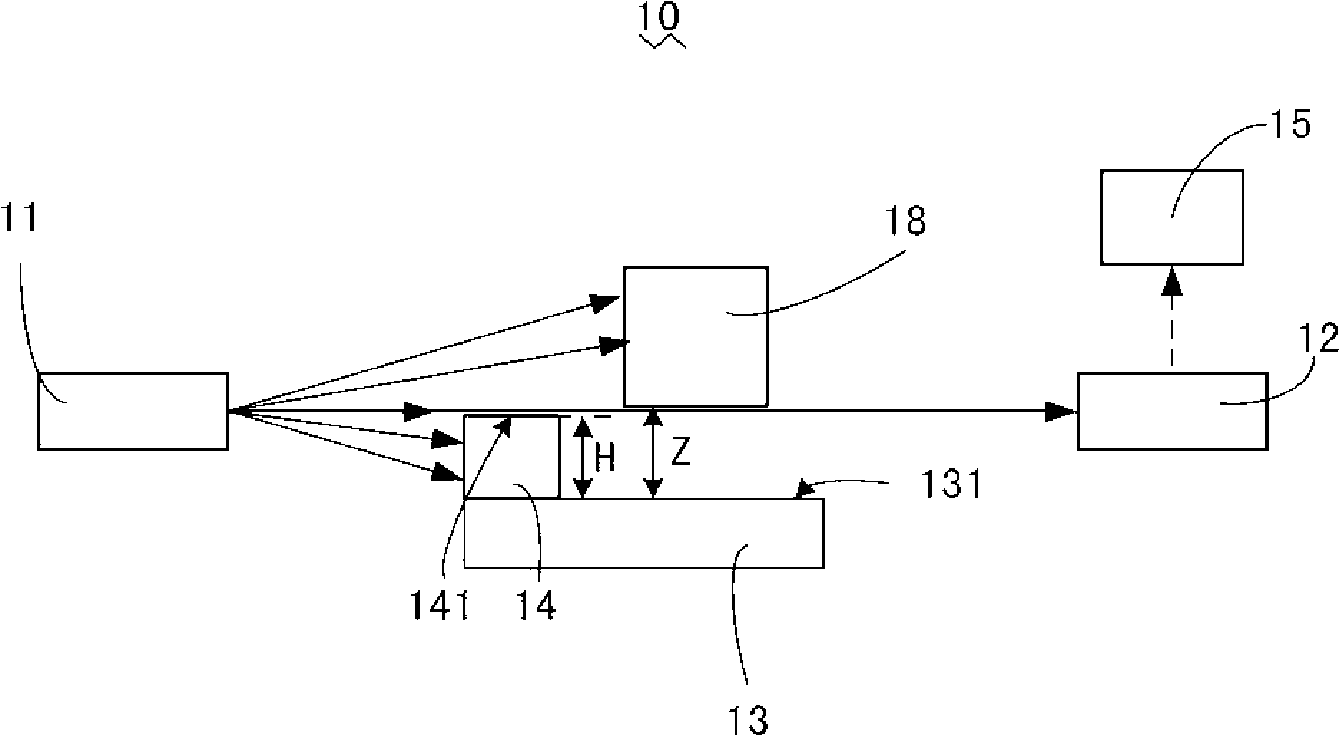
[0013] See figure 1 , a schematic diagram of the working principle of the flatness detection device 10 according to the preferred embodiment 1 of the present invention. The flatness detection device 10 includes a light emitting unit 11 , a light receiving unit 12 , an object stage 13 , a light shielding unit 14 and a processing unit 15 . The light receiving unit 12 can be arranged opposite to the light emitting unit 11 . In this embodiment, the light emitting center of the light emitting unit 11 and the light receiving center of the light receiving unit 12 are on the same straight line. The stage 13 can be located between the light emitting unit 11 and the light receiving unit 12 , and is used for carrying the workpiece 18 to be measured. The light-shielding unit 14 is also located between the light-emitting unit 11 and the light-receivi...


PUM


Abstract

The invention discloses a flatness detection device, which includes a light emission unit, a light receive unit, an object stage, a shading unit and a process unit. The light receive unit is relate to the light emission unit. The object stage is between the light emission unit and the light receive unit and is used for loading a test work-piece. The shading unit is located between the light emission unit and the light receive unit, which is used for forming a light gap coordinate with a test surface between a vertex and a lowest point of the test surface of the test work-piece when detected. The process unit is connected to the light receive unit, which is used for processing light information received by the light receive unit. The invention also discloses a flatness detection method. The flatness detection device has the advantages of high accuracy and avoiding bumping with the test work-piece.

Description

technical field [0001] The invention relates to a detection device, in particular to a flatness detection device using the photoelectric principle, and also to a flatness detection method. Background technique [0002] In mechanical processing, it is often necessary to inspect the flatness of the surface of the processed workpiece to verify whether the shape of the product is qualified. In the traditional flatness detection method, the method of adding a feeler gauge to the platform is more commonly used. [0003] The process of flatness detection by means of platform plus feeler gauge is as follows: first, place the workpiece on a reference platform; then use feeler gauge to check whether the flatness value of the workpiece is qualified. The method of adding a feeler gauge to the platform has the advantages of simple working principle and low equipment cost. [0004] However, the flatness of the workpiece is detected by using the platform plus a feeler gauge, and the dete...

Claims


Application Information

Patent Timeline
Patent Type & Authority Applications(China)
IPC IPC(8): G01B11/30
CPCG01B11/306
Inventor 蒋顺董桂利
Owner HONG FU JIN PRECISION IND (SHENZHEN) CO LTD
Why Eureka
Try Eureka