Engine experimental stand

A test bench and engine technology, which is applied in the direction of engine testing, engine base, machine/structural component testing, etc., can solve the problems that the working conditions of the engine cannot be reproduced, and achieve the effect of simple structure

Active Publication Date: 2008-09-17
CHERY AUTOMOBILE CO LTD
View PDF0 Cites 8 Cited by
  • Summary
  • Abstract
  • Description
  • Claims
  • Application Information

AI Technical Summary

Problems solved by technology

Its shortcoming is that the test bench can only simulate the steady-state condition of the engine in a horizontal state, and cannot reproduce the working conditions of the engine in a dynamic working state such as a tilted state.

Method used


Image

  • Engine experimental stand
  • Engine experimental stand
  • Engine experimental stand

Examples


Embodiment 1

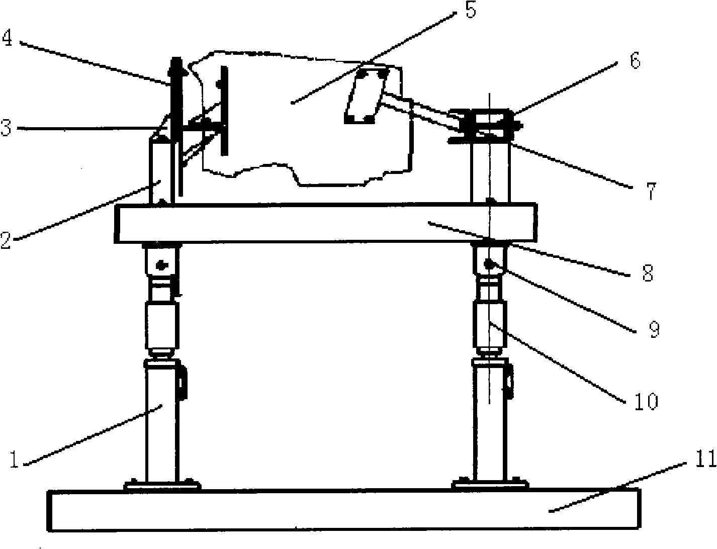
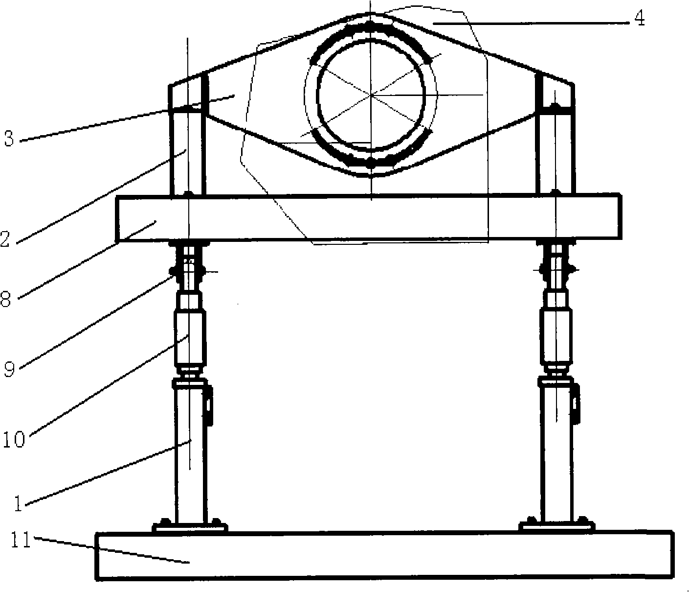
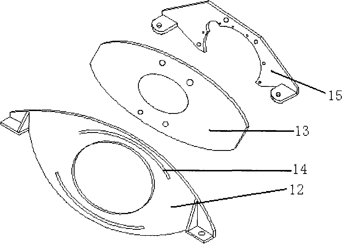
[0019] Example 1 in figure 1 , 2 , 3, 4, 5, 6, a kind of engine test bench, two channel steels with sliding grooves are fixed on the ground to form the chute floor 11, and 4 grooves are installed on the sliding grooves of the 11 channel steels on the chute floor Movable pillars 1, the upper part of these movable pillars 1 is connected with a height-adjusting pillar 10 that can be adjusted in height. The height-adjusting pillar 10 is a two-stage structure of stud screw holes, which is adjusted by screwing the studs into the screw holes of the movable pillars. Then lock it by locking bolt 18. The front and rear inclination between the accessories of the engine and the flywheel can be adjusted by adjusting the distance of 4 movable pillars 1 and the height of the raised pillar 10. By measuring the height difference of 4 movable pillars 1 and the distance between them, the engine The angle of inclination before and after can be calculated by formula. Connected above the height-...


PUM


Abstract

An engine test table is composed by facilitating a group of movable pillars on a chute steel plate; the movable pillars are connected with the engine to be tested via connecting support device; the connecting support device is a device for fixing the engine after leading it to rotate along the axial center line. The connecting support device is respectively composed of a support A and a support B. The support A is formed in an index plate pattern by sequentially connecting the chute steel plate, the rotating steel plate and the engine connecting plate. The support B is composed by connecting a rotating beam and a beam, the middle part of each beam comprises a center hole via which the bolts pass to integrally connect the beams. The movable pillar is an adjustable pillar composed of a two-segment structure with bolt and bolt hole, capable of adjusting forward and backward height and position of the engine. By only using the device of index plate type for fixing and connecting the engine after leading it to rotate along the axial center line, and height adjusting pillar composed of a two-segment structure with bolt and bolt hole, the invention can adjust the rotating angle of axial center line along which the engine rotates and adjust the forward and backward height and position of the engine with simple, reliable and safe structure.

Description

technical field [0001] The invention relates to a power plant test bench, in particular to an automobile engine test bench device. Background technique [0002] At present, the main structure of the engine test stand is to include a group of movable pillars on the chute floor, and the pillars are connected to the test engine through the connecting bracket. Its disadvantage is that the test bench can only simulate the steady-state condition of the engine for testing, and cannot reproduce the working conditions when the engine is in a dynamic working state such as an inclined state. Therefore, it is an urgent problem to design an automobile engine test bench device that can reproduce the dynamic working state of the engine. Contents of the invention [0003] The technical problem to be solved by the present invention is to provide a safe and reliable engine test bench simulating the dynamic working state of the engine, with adjustable angle position, simple structure, in or...

Claims


Application Information

Patent Timeline
Patent Type & Authority Applications(China)
IPC IPC(8): G01M15/00F16M5/00
Inventor 曹金柱李红雨张福明
Owner CHERY AUTOMOBILE CO LTD
Why Eureka
Try Eureka