An electronic transformer

An electronic transformer and external circuit technology, applied in the direction of transformer/inductor magnetic core, transformer/inductor coil/winding/connection, electrical component structure association, etc., can solve problems such as instability, temperature rise, and cost increase

Inactive Publication Date: 2008-09-17
SHANGHAI CHARLES ELECTRONICS
View PDF0 Cites 2 Cited by
  • Summary
  • Abstract
  • Description
  • Claims
  • Application Information

AI Technical Summary

Problems solved by technology

[0002] The traditional electronic transformer uses a U-shaped magnetic core, and cooperates with the winding frames with through holes on the left and right sides. The electronic transformer with this structure also needs to use steel clips to fix the magnetic c...

Method used


Image

  • An electronic transformer
  • An electronic transformer
  • An electronic transformer

Examples


Embodiment Construction

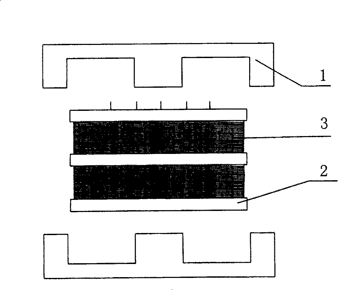
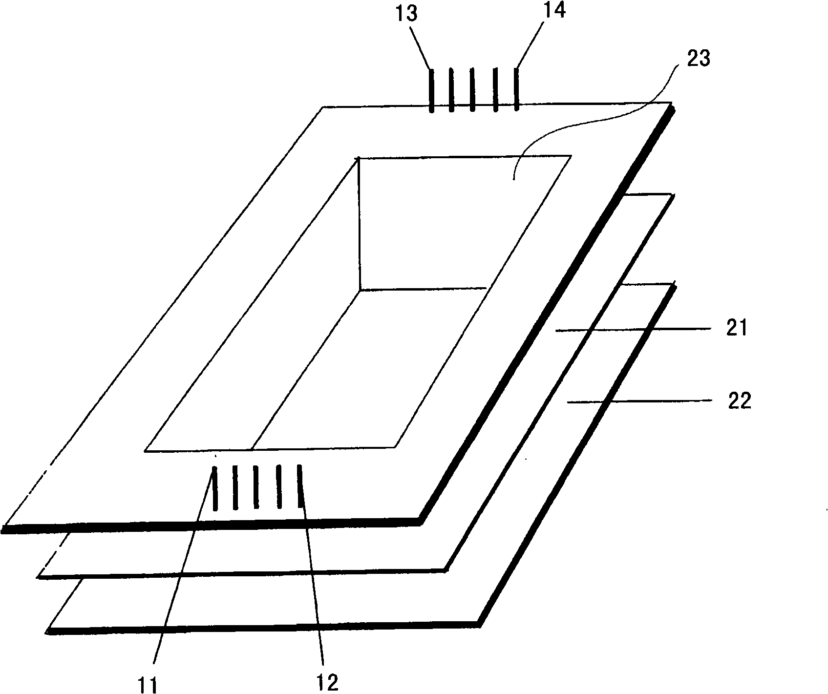
[0017] Please see attached figure 1 As shown, the electronic transformer of the present invention includes a magnetic core 1, a bobbin 2 and a coil 3, wherein the magnetic core 1 is formed by two E-shaped magnetic cores connected in a Japanese-shaped combination, and the central column of the magnetic core 1 is inserted into the bobbin In 2, the outer frame of the magnetic core 1 encloses the winding frame 2 and the coil 3, and the cross section of the winding frame 2 is a back-shaped structure, which is divided into upper and lower layers of winding slots 21 and 22, and the coil 3 is respectively wound on the wire slots 21 and 22 within. Hollow through-holes 23 are provided on the top and bottom surfaces of the bobbin frame 2, and lead joints 11-14 are arranged at opposite positions on the bottom surface of the bobbin frame 2, and the joints of the coils are respectively welded on the lead joints.

[0018] When assembling the electronic transformer of the present invention, ...


PUM


Abstract

The invention discloses a electronic transformer, characterized in that the electronic transformer comprises: a coil winding rack, above or below which through holes are provided, and a plurality of pins are provided at a bottom face of the coil winding rack; two E type iron cores whose middle posts are respectively inserted into the upper and lower through holes of the coil winding rack; a winding, which is wound on the coil winding rack, and connected with an external circuit respectively through the pins. The invention replaces the traditional U type magnet iron by the E type iron core and saves structure of a steel clamp, which not only reduces cost, but also greatly lessens the magnetic conductivity.

Description

technical field [0001] The invention relates to an electronic transformer. Background technique [0002] The traditional electronic transformer uses a U-shaped magnetic core, and cooperates with the winding frames with through holes on the left and right sides. The electronic transformer with this structure also needs to use steel clips to fix the magnetic core, which increases the cost. The magnetic rate is as high as 5,000-10,000, and it is easy to cause the temperature to rise during use, which will lead to unstable inductance, and then affect the unstable performance of the entire product. Contents of the invention [0003] In view of the above problems, the present invention proposes an electronic transformer with an improved magnetic core structure. Specifically, the traditional U-shaped magnetic core is replaced by an E-shaped magnetic core, which saves the structure of the steel clip, thereby not only reducing the cost , but also brought a significant reduction in...

Claims


Application Information

Patent Timeline
IPC IPC(8): H01F27/24H01F27/28H01F27/40
Inventor 杨晨
Owner SHANGHAI CHARLES ELECTRONICS
Why Eureka
Try Eureka