Optical fiber having low and uniform optical loss along the entire length and method for fabricating the same

An optical fiber preform and optical fiber technology, which is used in manufacturing tools, optical waveguides, glass manufacturing equipment, etc., can solve the problems of heat capacity loss, inability to determine the number of insertions, and the capillary can not be completely closed, and achieve low optical attenuation loss. Effect

Active Publication Date: 2008-09-17
STERLITE TECHNOLOGIES
View PDF2 Cites 7 Cited by
  • Summary
  • Abstract
  • Description
  • Claims
  • Application Information

AI Technical Summary

Problems solved by technology

One disadvantage is that the number of insertions cannot be determined until the processing starts, making the completion of the overall processing indeterminate, since the duration of the processing completion is not known until the processing is complete
The second disadvantage is that the capillary is not completely closed
[0019] The complete withdrawal of the preform during the sintering and / or shrinking treatment steps according to the prior art methods described above also has the disadvantage of a loss of heat capacity

Method used


Image

  • Optical fiber having low and uniform optical loss along the entire length and method for fabricating the same
  • Optical fiber having low and uniform optical loss along the entire length and method for fabricating the same
  • Optical fiber having low and uniform optical loss along the entire length and method for fabricating the same

Examples


specific Embodiment approach

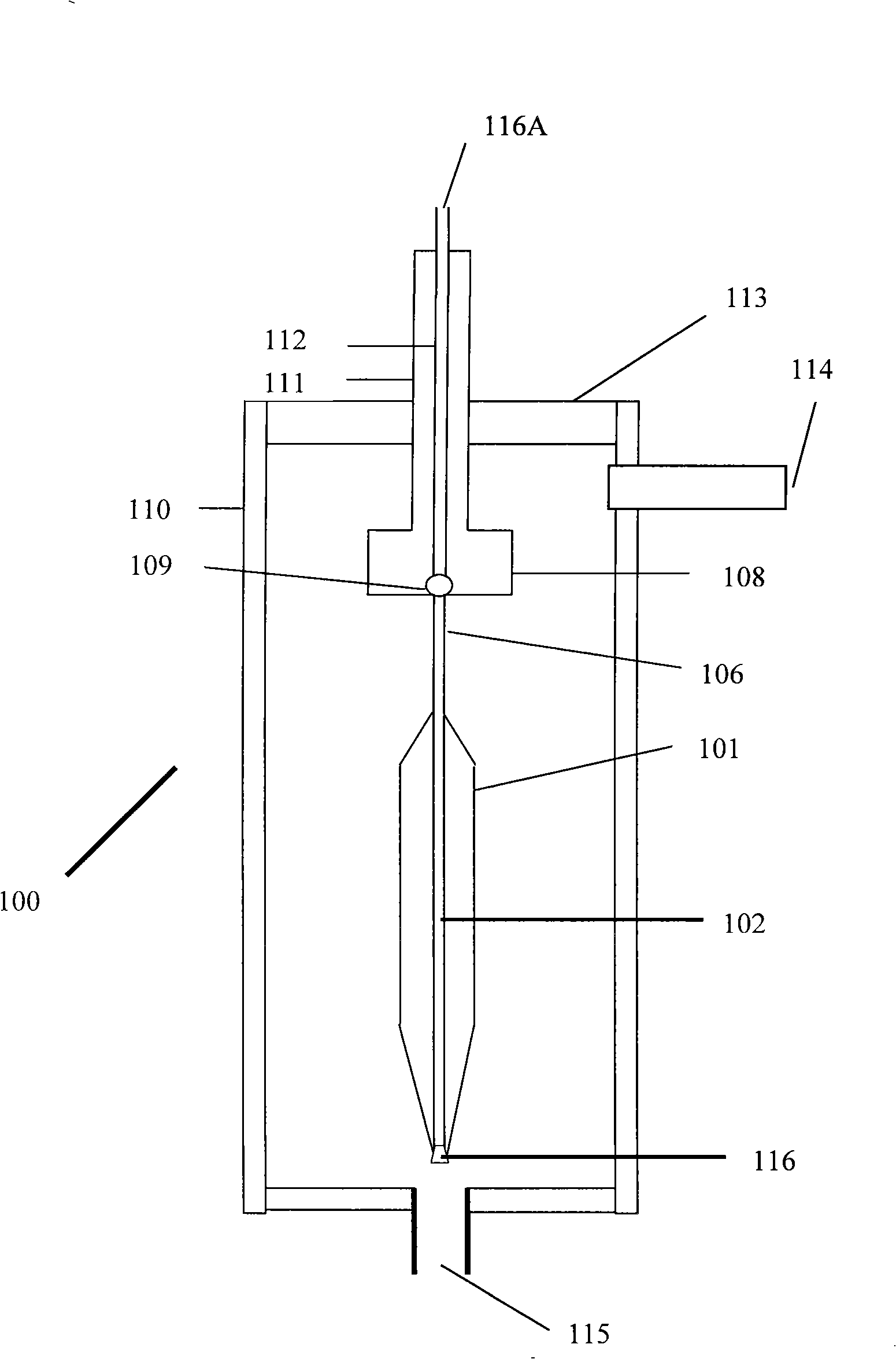
[0091] The processing of the present invention starts in the manner described above. Dehydration treatment step with gas such as Cl 2 , CCl 4 、SiCl 4 、GeCl 4 or any combination thereof and inert gases such as He, Ar, N that also act as heat carriers 2 To promote the effective dehydration and sintering of the hollow soot porous body 101. These gases are fed into the furnace 100 through an inlet 115 suitably located on the furnace, preferably near the bottom of the closed tube 110 . The top end of the closed tube 110 is closed with a cover 113 to achieve the optimum temperature profile inside the closed tube 110, for example, the curve 117( Figure 5 ), and maintain the same temperature profile during the dehydration, and simultaneous sintering and shrinking process steps, and avoid gas leakage from the closed tube 110 to the external environment. A suction port 114 is suitably located near the top of the closed tube 110 so that gas is evacuated from the closed tube 110 wh...

example 1

[0111] Example 1 (Prior Art Method)

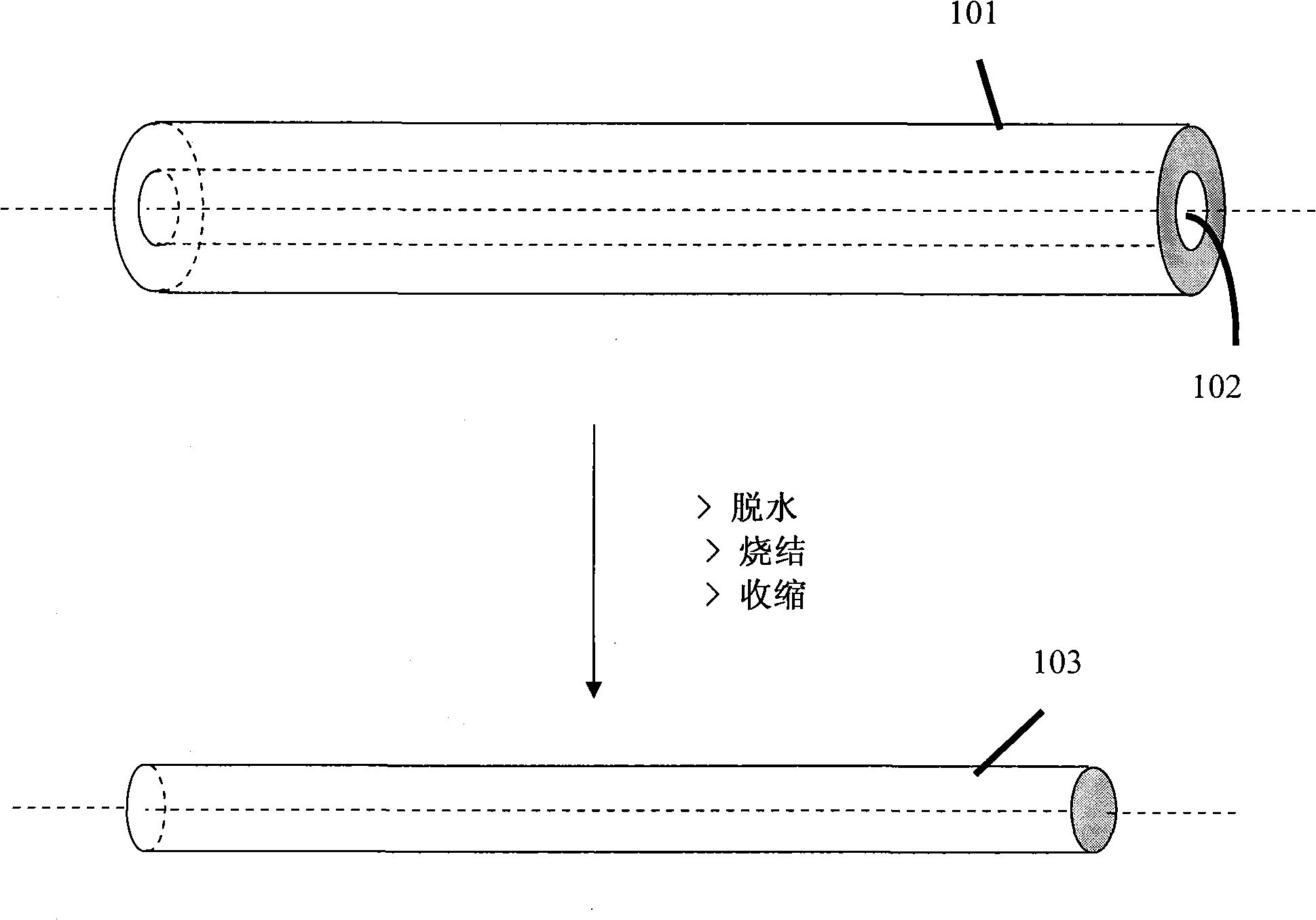
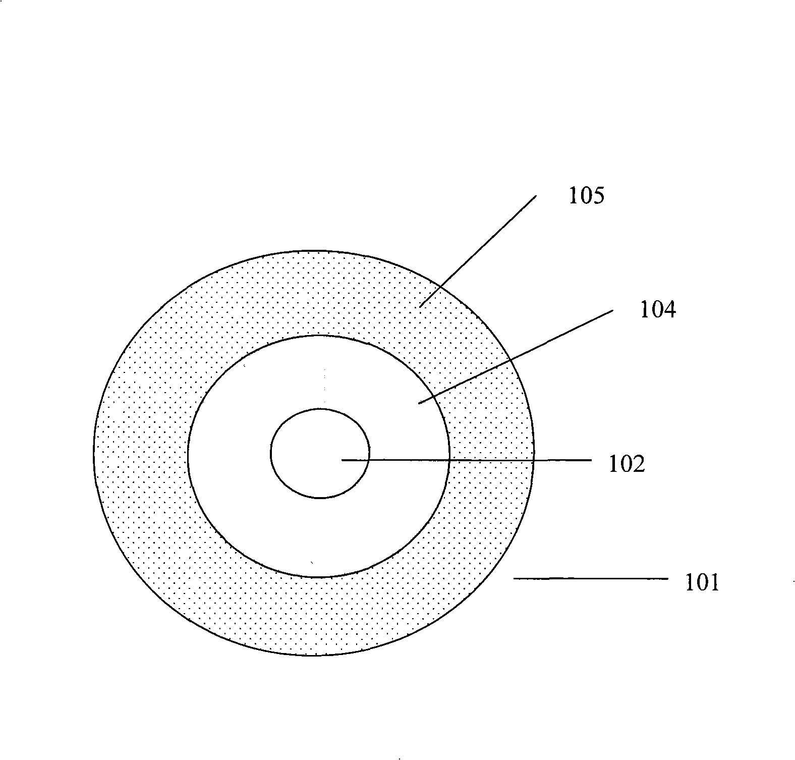
[0112] Soot deposition is accomplished on a tapered cylindrical member by known methods to produce a soot porous body having the desired soot mandrel diameter and soot cladding diameter. The tapered cylindrical member is separated from the soot porous body to have a capillary diameter ranging from about 6 mm to about 8 mm from the bottom end to the top end of the hollow soot porous body. Before inserting the hollow soot porous body into the sintering furnace, the capillary of the hollow soot porous body was cleaned with N 2 Purge for approximately 5 minutes at a flow rate of approximately 20 SLPM to ensure that no loose soot particles are present in the capillary. For dehydration, the hollow soot porous body is inserted into the first heating zone of the sintering furnace, which is maintained at a temperature in the range of about 1050°C to about 1150°C. During the dehydration process, from the bottom end of the sintering furnace, the He...

example 2

[0113] Example 2 (this method)

[0114] Soot deposition is accomplished on a tapered cylindrical member by known methods to produce a soot porous body having the desired soot mandrel diameter and soot cladding diameter. The tapered cylindrical member is separated from the soot porous body such that the hollow soot porous body has a capillary diameter ranging from about 6 mm to about 8 mm from the bottom end to the top end. Before inserting the hollow soot porous body into the sintering furnace, the capillary of the hollow soot porous body was cleaned with N 2 Purge for approximately 5 minutes at a flow rate of approximately 20 SLPM to ensure that no loose soot particles are present in the capillary. For dehydration, the hollow soot porous body is inserted into the first heating zone of the sintering furnace, which is maintained at a temperature in the range of about 1050°C to about 1150°C. During the dehydration process, from the bottom end of the sintering furnace, the He f...


PUM

PropertyMeasurementUnit
dispersion valueaaaaaaaaaa
lengthaaaaaaaaaa

Abstract

A method for producing optical fiber preform capable of producing optical fiber having low and uniform optical attenuation loss along its entire length including the top end portion is provided. The method comprises carrying out simultaneously sintering and collapsing steps by inserting the dehydrated hollow soot porous body with predetermined speed in hot zone of the furnace till its top end reaches the hot zone and is left for a predetermined duration thereafter the preform is uplifted for a predetermined length at a predetermined speed to avoid heat loss in the optical preform and re-inserted in the hot zone of sintering furnace at a predetermined speed and left for predetermined duration to result in formation of the preform having collapsed capillary including at its top end.

Description

technical field [0001] The present invention relates to an optical fiber having low and uniform optical loss along its entire length and a method of making the same. More particularly, the present invention relates to an optical fiber preform capable of producing an optical fiber having low and uniform optical loss along its entire length including its tip portion, and a method for producing the same. Background technique [0002] Optical fiber is inherently universal as a medium for all forms of information transmission, be it voice, video or data. [0003] The main purpose of the telecommunications industry is to transmit more information over longer distances in a shorter period of time. This object is achieved by optical fibers having both low and uniform optical attenuation losses, especially in the region of 1360-1460 nm (E-band region). [0004] Typically, single-mode optical fibers are used for data transmission in the wavelength region range from about 1300 nm to ...

Claims


Application Information

Patent Timeline
Patent Type & Authority Applications(China)
IPC IPC(8): C03B37/018G02B6/10
CPCC03B37/01473C03B37/01486C03B37/01446
Inventor 斯里纳·达亚南丹桑克特·沙阿拉维基兰·阿查里雅杰钢·米拉斯
Owner STERLITE TECHNOLOGIES
Why Eureka
Try Eureka