Touch panel

A touch panel and panel technology, which is applied to instruments, electrical digital data processing, and input/output processes of data processing, etc., can solve the problems of complex structure of touch panel devices, and achieve the effects of accurate operation, easy manufacturing and simple structure.

Inactive Publication Date: 2008-09-17
SMK CO LTD
View PDF3 Cites 15 Cited by
  • Summary
  • Abstract
  • Description
  • Claims
  • Application Information

AI Technical Summary

Problems solved by technology

However, in order to provide this forced feedback function on the touch panel, a device for vibrating the panel is also required, which leads to a problem that the structure of the touch panel device becomes more complicated.

Method used


Image

  • Touch panel
  • Touch panel
  • Touch panel

Examples


Embodiment Construction

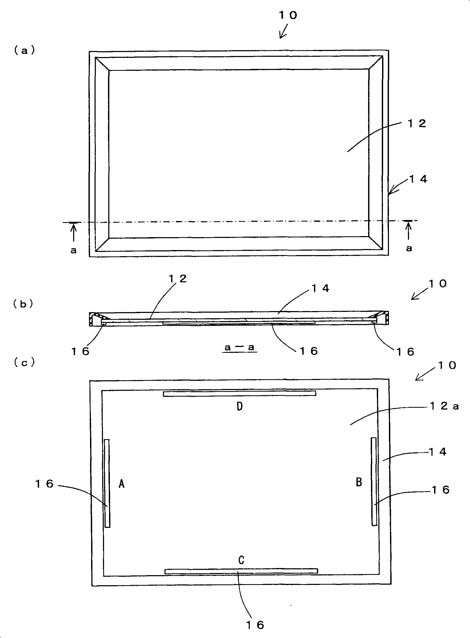
[0030] Hereinafter, embodiments of the present invention will be described with reference to the drawings. Figure 1 to Figure 4 It is a figure which shows one Embodiment of this invention, and the touch panel 10 of this embodiment is used as an input device used for a car navigation apparatus, an ATM, a ticket vending machine, various operation panels, and the like.

[0031] The touch panel 10 includes a square panel 12 such as a transparent resin substrate and a glass substrate, and a frame 14 that holds the periphery of the panel 12 . On the panel 12 , elongated piezoelectric elements 16 are integrally fixed along the four sides of the back surface 12 a . The length of the piezoelectric element 16 does not need to be the full length of one side of the panel 12, but is preferably about 1 / 2 or more of the length of one side.

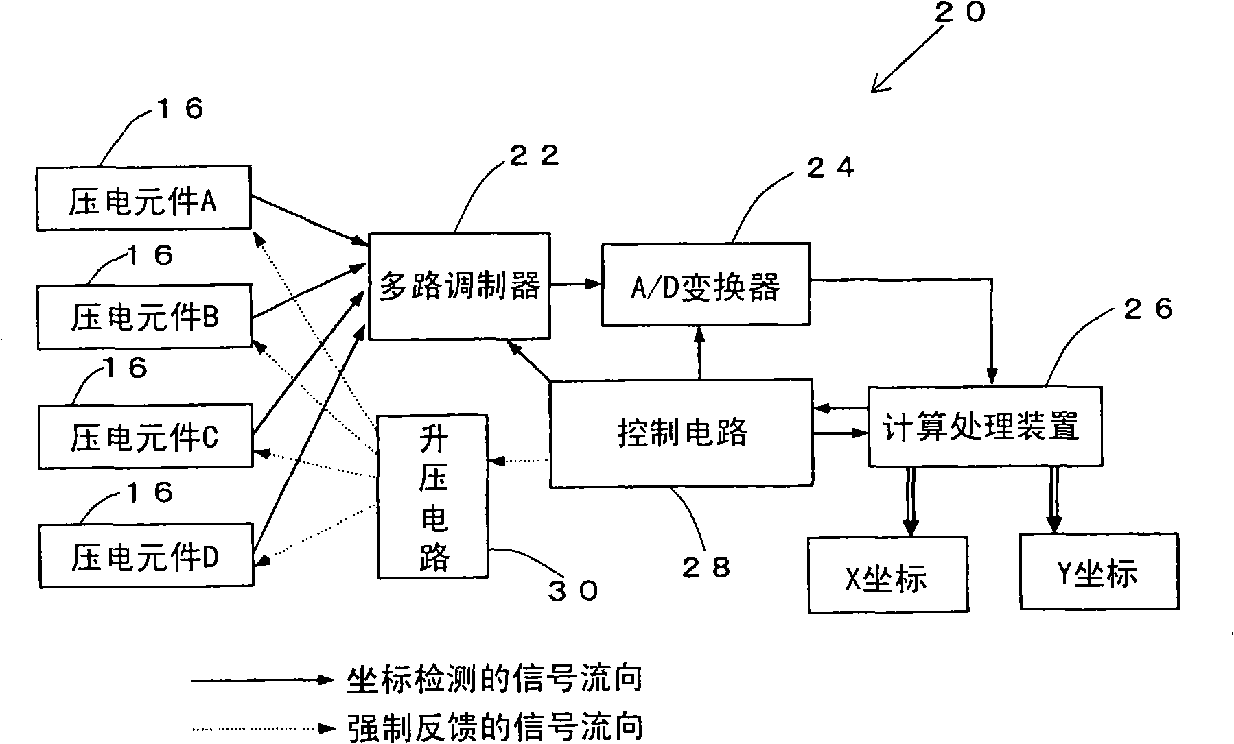
[0032] The piezoelectric element 16 of the touch panel 10 is connected to a pressing position detection circuit 20 as a pressing position calculating ...


PUM


Abstract

A touch panel having a simple structure enabling accurate and reliable operation. The touch panel has a panel (12) constituting a display screen etc.; long piezoelectric elements (16) arranged and fixed along at least two intersecting sides of the panel (12); a pressing position detecting circuit for calculating the pressing position in the panel (12) based on an output from a piezoelectric element (16); and a step-up circuit, i.e. a piezoelectric element drive means, for oscillating the piezoelectric element (16) by applying a voltage to it when the pressing position in the panel (12) is calculated by both the piezoelectric element (16) and the pressing position detecting circuit.

Description

technical field [0001] The present invention relates to a touch panel used as an input device provided in a display, an operation unit, or the like of various electronic devices. Background technique [0002] Conventionally, electronic equipment having a touch panel function on a display surface has been widely used. As one of the structures of the touch panel, there is a resistive film type touch panel. In this touch panel, an ITO (indium oxide) film is provided in a predetermined pattern on the surface of the touch panel glass, an electrode is connected to an end portion of the ITO film, and a peripheral portion is covered with a protective layer. A dot spacer is provided between the upper and lower panels on which the ITO film is deposited, and when pressed, the ITO films of the upper and lower panels come into contact, and the position on the panel is detected by the resistance value at this time. [0003] However, in the touch panel of this type, the ITO films of the ...

Claims


Application Information

Patent Timeline
Patent Type & Authority Applications(China)
IPC IPC(8): G06F3/041G06F3/042
CPCG06F3/0421G06F3/0414G06F3/016G06F2203/04106G06F3/04142
Inventor 南部元俊岩胁信也若林俊行
Owner SMK CO LTD
Why Eureka
Try Eureka