Method and apparatus for solder ball placement

A solder ball and template technology, applied in the field of ball grid array, can solve the problem of insufficient accurate positioning of solder balls

Inactive Publication Date: 2011-06-22
ROKKO VENTURES PTE LTD
View PDF5 Cites 2 Cited by
  • Summary
  • Abstract
  • Description
  • Claims
  • Application Information

AI Technical Summary

Problems solved by technology

Although bonding and separation of solder balls is controllable under sufficiently high vibration conditions, precise positioning of solder balls is still insufficient

Method used


Image

  • Method and apparatus for solder ball placement
  • Method and apparatus for solder ball placement
  • Method and apparatus for solder ball placement

Examples


Embodiment Construction

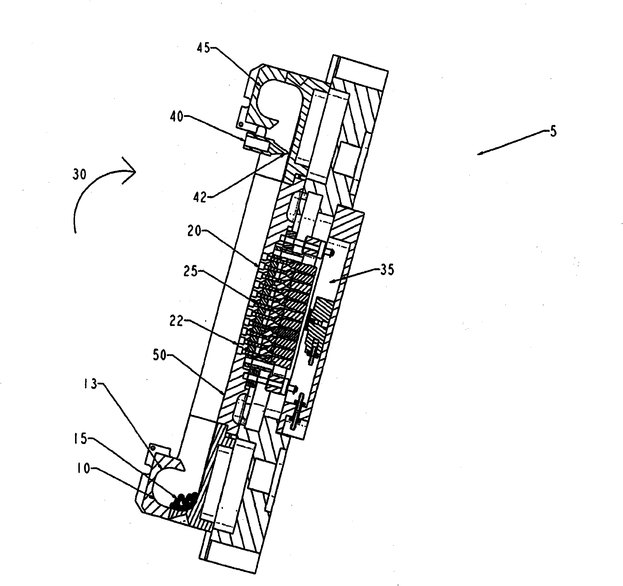
[0031] figure 1 The first stage of the method according to the invention is shown. At this stage, the solder ball mounting module 5 is in the first position ready to fill the recess 20 in the ball grid array template 22. In this first position, the solder ball 15 is located in the storage area, in this case the solder ball holding area 10. The holding area 10 is arranged such that the solder balls 15 are held in the holding area under varying angle conditions of the module 5 by the partially enclosed surface 13.

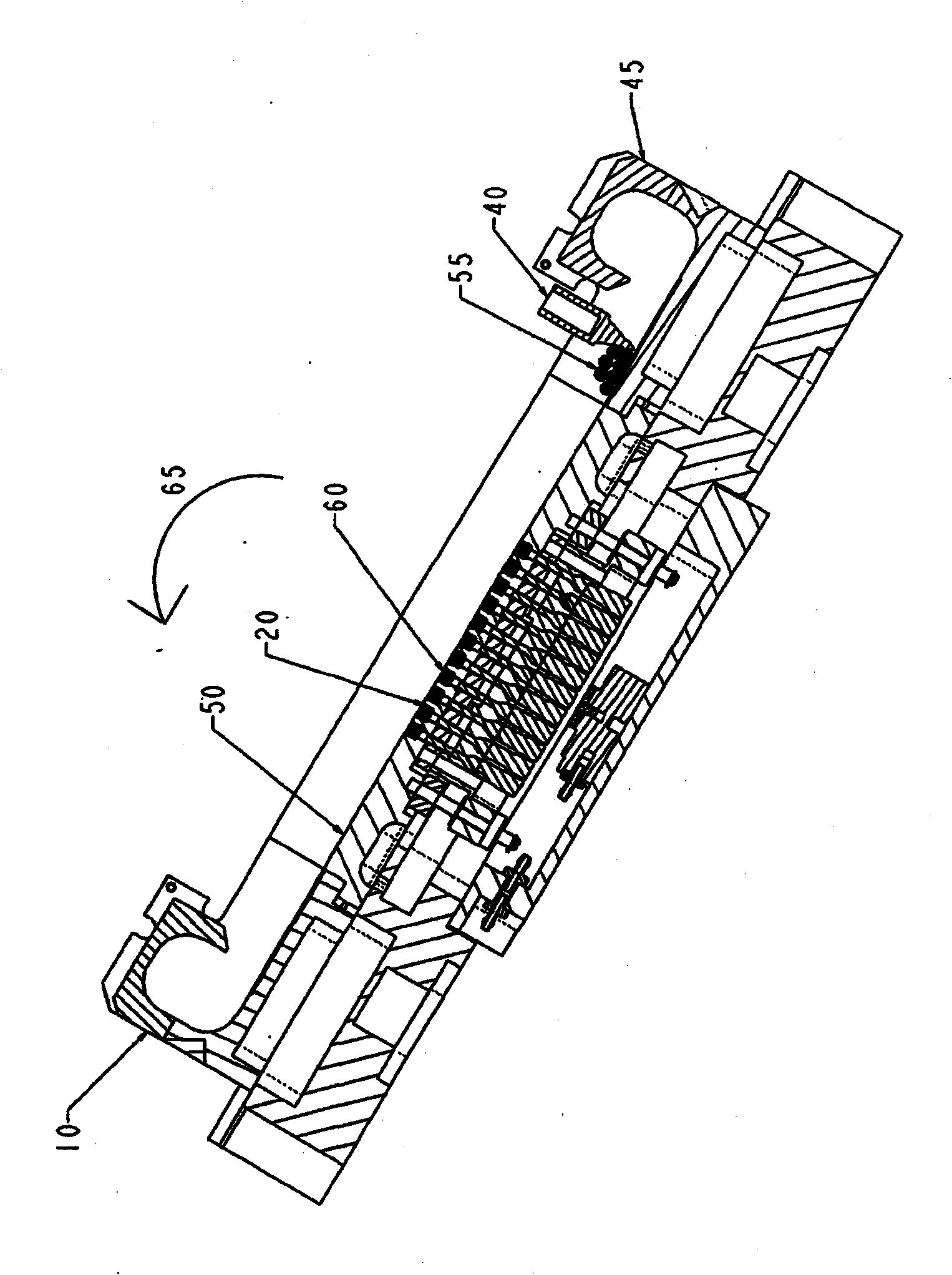
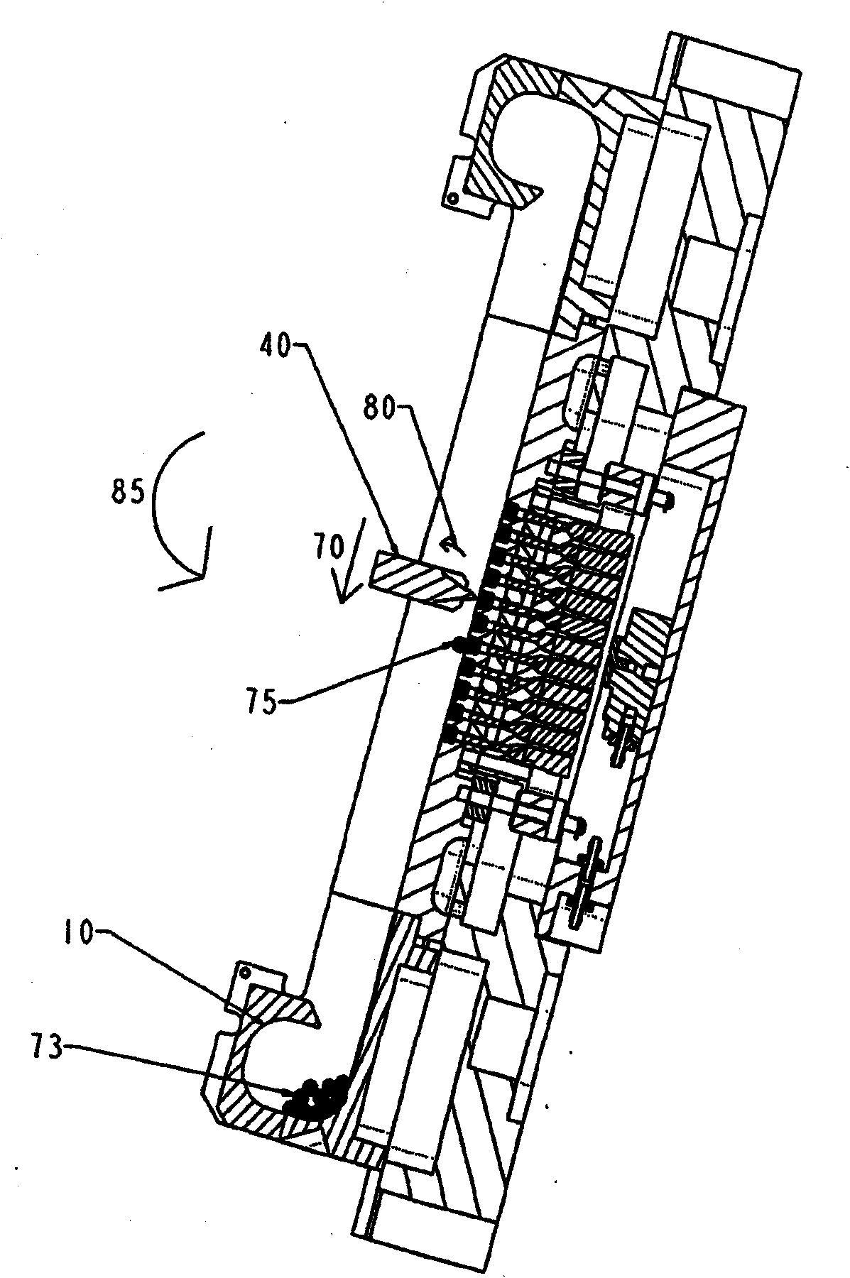
[0032] The module 5 includes a continuous surface 50 on which the solder balls 15 can flow to pass through the template 22. At the opposite end of the surface 50 is a second solder ball holding area 45 for receiving the solder balls as they flow through the template 22 and also collecting the solder balls. Therefore, within the rotation range of the module 5, the respective holding areas 10, 45 can hold the solder balls without flowing out of the module 5, but still ...


PUM


Abstract

A solder ball mounting module comprising a solder ball template (22) having an array of recesses (20), each recess being in communication with a vacuum source (35), and each arranged to receive a solder ball (15); wherein each recess further includes an ejector pin (110) for selectively ejecting the respective solder ball engaged therein.

Description

Technical field [0001] The invention relates to a ball grid array. Specifically, the present invention relates to a method and apparatus for arranging solder balls into a ball grid array on the substrate before dividing the substrate. Background technique [0002] The ball grid array is used to receive solder balls, which are used as electrodes for bonding with integrated circuits. Usually when the solder balls are arranged, the integrated circuit is arranged as part of a larger substrate and therefore before it is divided into individual units. [0003] When arranging the solder balls on the substrate so as to align with each individual unit, the solder balls are usually arranged in a device of a predetermined arrangement and then raised using a picker head for final arrangement on the substrate. [0004] The nature of the solder ball itself causes a problem. In many cases, the diameter of the solder ball is less than 0.5 mm, so it is subjected to electrostatic force, and if mois...

Claims


Application Information

Patent Timeline
Patent Type & Authority Applications(China)
IPC IPC(8): B23K3/06
CPCB23K3/0623H05K3/3478
Inventor 安松隆林镍盛邱锦鸿白德祥
Owner ROKKO VENTURES PTE LTD
Why Eureka
Try Eureka