
Liquid crystal device, electronic apparatus and position detecting method

A liquid crystal device and liquid crystal technology, which are applied in the direction of electrical digital data processing, instruments, and the input/output process of data processing, etc., can solve the problems of inductive noise, decrease in the accuracy of detection electrodes, and decrease in detection accuracy.

Inactive Publication Date: 2008-09-24
JAPAN DISPLAY INC
View PDF4 Cites 33 Cited by
  • Summary
  • Abstract
  • Description
  • Claims
  • Application Information

AI Technical Summary

Problems solved by technology

[0007] However, there is a parasitic capacitance between the detection electrode and the electrode or wiring of the liquid crystal device
Therefore, in liquid crystal devices, when various signals used for image display fluctuate, noise is induced in the detection electrodes.
The noise of the detection electrode causes the accuracy of specifying the position of the pointer to decrease
In view of the above, an object of the present invention is to solve problems such as suppressing a decrease in detection accuracy due to noise of a detection electrode.

Method used


Image

  • Liquid crystal device, electronic apparatus and position detecting method
  • Liquid crystal device, electronic apparatus and position detecting method
  • Liquid crystal device, electronic apparatus and position detecting method

Examples


Embodiment approach

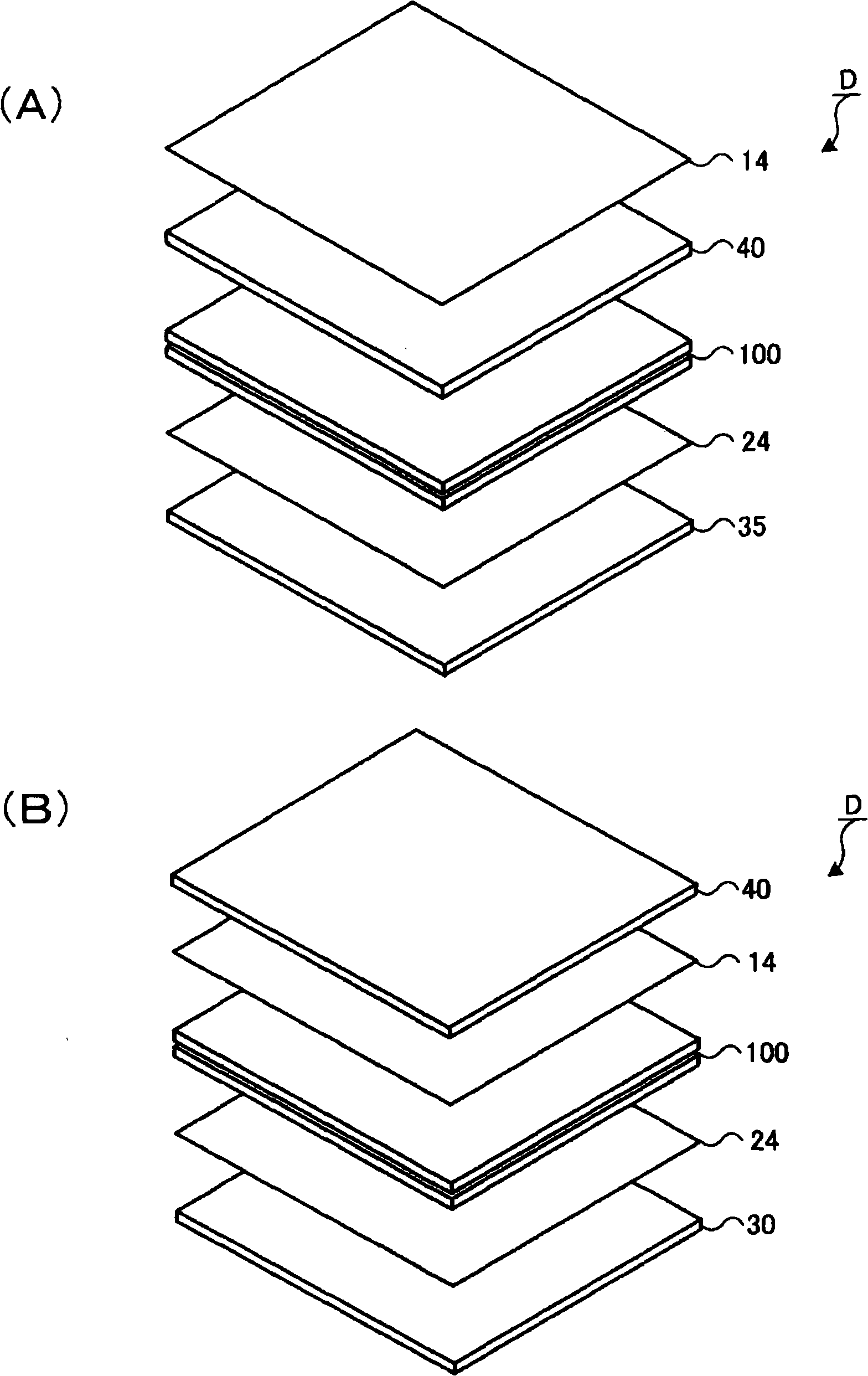
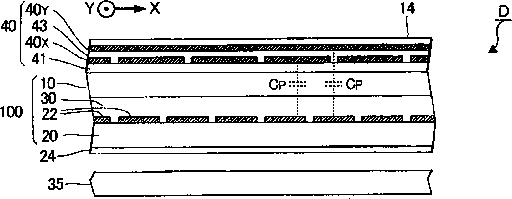
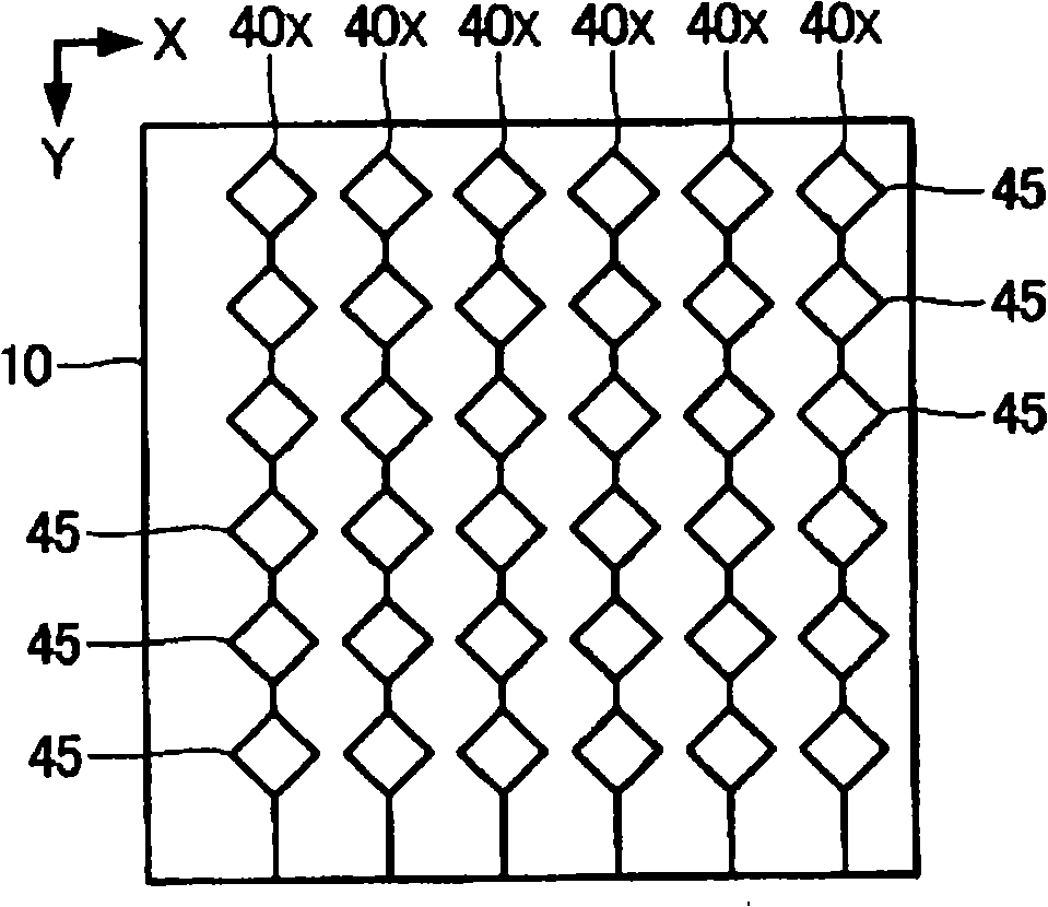
[0036] figure 1 It is an exploded perspective view showing the configuration of the liquid crystal device according to the embodiment of the present invention. The liquid crystal device D is a liquid crystal display device with a capacitive touch panel, and has a function of displaying images by using the optical action of liquid crystals, and a pointer (finger or pen) that detects contact with or approaching the front of the liquid crystal device D based on changes in capacitance. function of position. Such as figure 1 As shown in (A), the liquid crystal device D has a liquid crystal panel 100 and a touch screen 40 . On the upper surface of the touch panel 40, a polarizing plate 14 is provided, and on the lower surface of the liquid crystal panel 100, a polarizing plate 24 is provided. Further, a backlight 35 is provided below the polarizing plate 24 . In addition, light from the backlight 35 is optically modulated by the liquid crystal panel 100 . In addition, the liqui...


PUM


Abstract

This invention provides a liquid crystal device (D) including a liquid crystal panel (100), a touch panel (40). A position signal generating device (60) orderly selects a plurality of electrons for detection formed in the touch panel (40) and generates a shielding signal for specifying the display area superposed with the selected electrons for detection. A display control circuit (120) generates an output image data GD2 for displacing a brightness level of the display region appointed by the shielding signal to a black level and output to a drive circuit (110). So, a potential fixedly configured as a pixel electron under the electron for detection forming the selected object is able to greatly reduce the voice voltage superposed at the electron for detection along the brightness level change, so as to restrain the detection precision decreasing caused by the noise of the electron for detection.

Description

technical field [0001] The present invention relates to a technology for specifying a position where an object such as a finger or a pen (hereinafter referred to as "indicator") touches a display surface of a displayed image in a liquid crystal device. Background technique [0002] A liquid crystal device equipped with a capacitive touch panel has been proposed before. As disclosed in Patent Document 1 to Patent Document 4, electrodes for detection are formed on the viewing side of the liquid crystal device. The position of the indicator is specified based on the signal of the detected capacitance change of the detection electrode. [0003] Patent Document 1: Japanese Unexamined Patent Publication No. 5-19233 [0004] Patent Document 2: JP-A-8-44493 [0005] Patent Document 3: JP-A-2000-81610 [0006] Patent Document 4: Special Publication No. 2003-511799 [0007] However, there is a parasitic capacitance between the detection electrode and the electrode or wiring of th...

Claims


Application Information

Patent Timeline
Patent Type & Authority Applications(China)
IPC IPC(8): G02F1/133G09G3/20G06F3/044
CPCG06F3/0412G06F3/044G06F3/0445G06F3/0446
Inventor 宇都宫纯夫腰原健
Owner JAPAN DISPLAY INC
Learn More