Pressure sensor

a technology of pressure sensor and pressure sensor, which is applied in the direction of fluid pressure measurement, machines/engines, instruments, etc., can solve the problems of excessive pressure detection and insufficient reduction of output error of sensor element b>54/b>, and achieve the effect of suppressing the reduction of pressure detection accuracy and suppressing the change in relative positions of diaphragm and force transmitting member

Active Publication Date: 2005-01-18
TOYOTA CENT RES & DEV LAB INC
View PDF8 Cites 23 Cited by
  • Summary
  • Abstract
  • Description
  • Claims
  • Application Information

AI Technical Summary

Benefits of technology

The object of the present invention is to realize a pressure sensor wherein output error of a sensor element can be reduced even in a case where the pressure sensor is utilized in high temperature conditions.
According to this aspect, it is possible to suppress a change in relative positions of the diaphragm and the force transmitting member even when the pressure sensor is used in unstable conditions wherein vibrations or shocks are strong, and even when the pressure sensor is used for a long period of time. As a result, it is possible to suppress the reduction of accuracy in the pressure detection that tends to occur as a result of use in unstable conditions and as a result of use over a long period of time.

Problems solved by technology

However, there is a problem that the output error of the sensor element 54 still cannot be sufficiently reduced by the pressure sensor of the second prior art shown in FIG.
The pressure thus detected is excessively high.

Method used


Image

  • Pressure sensor
  • Pressure sensor
  • Pressure sensor

Examples


first embodiment

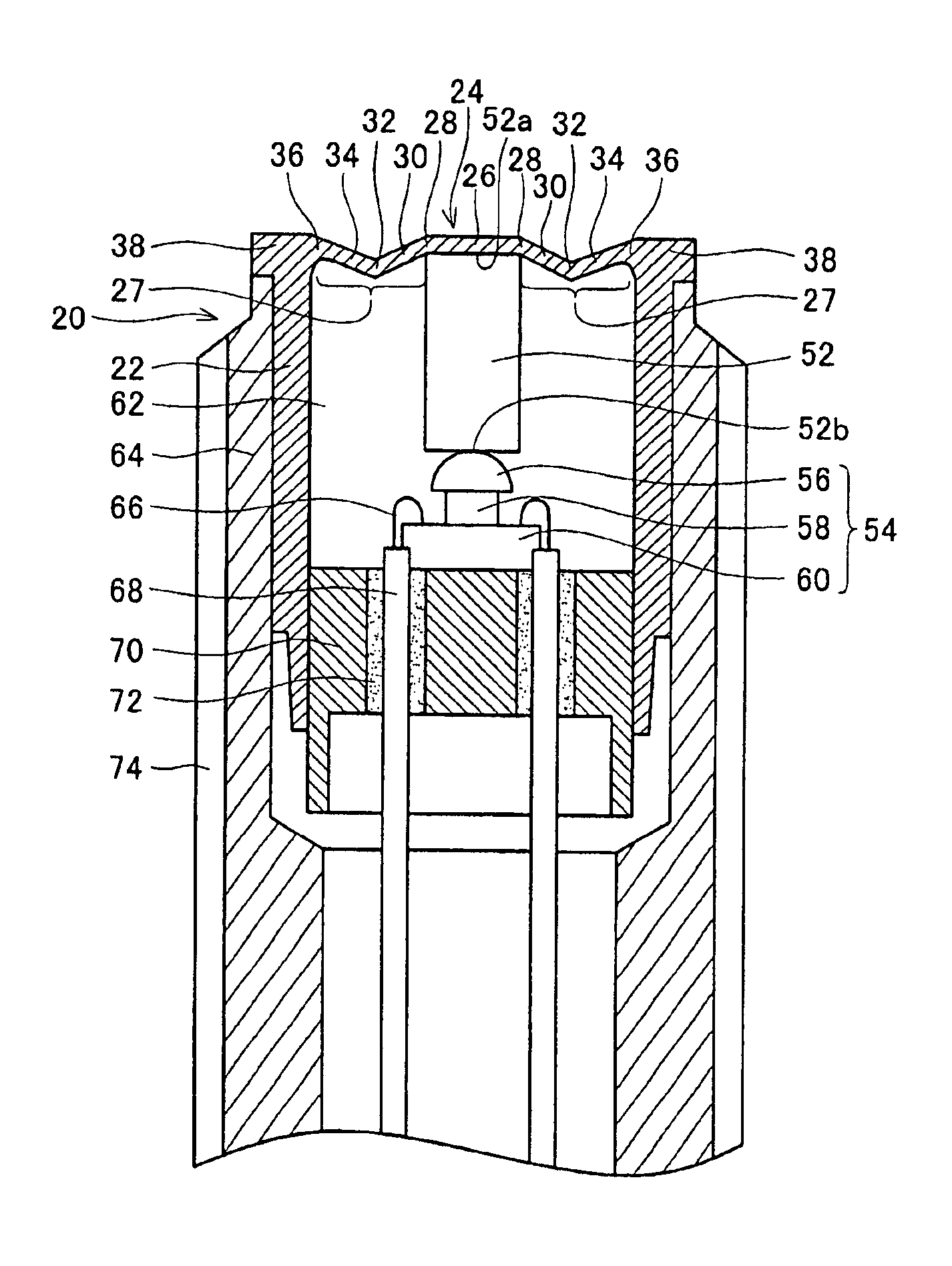
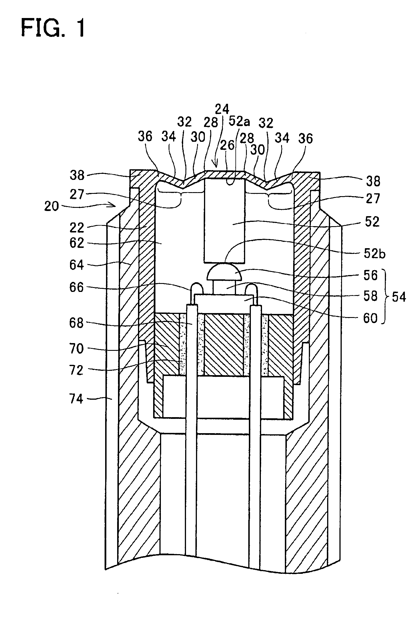
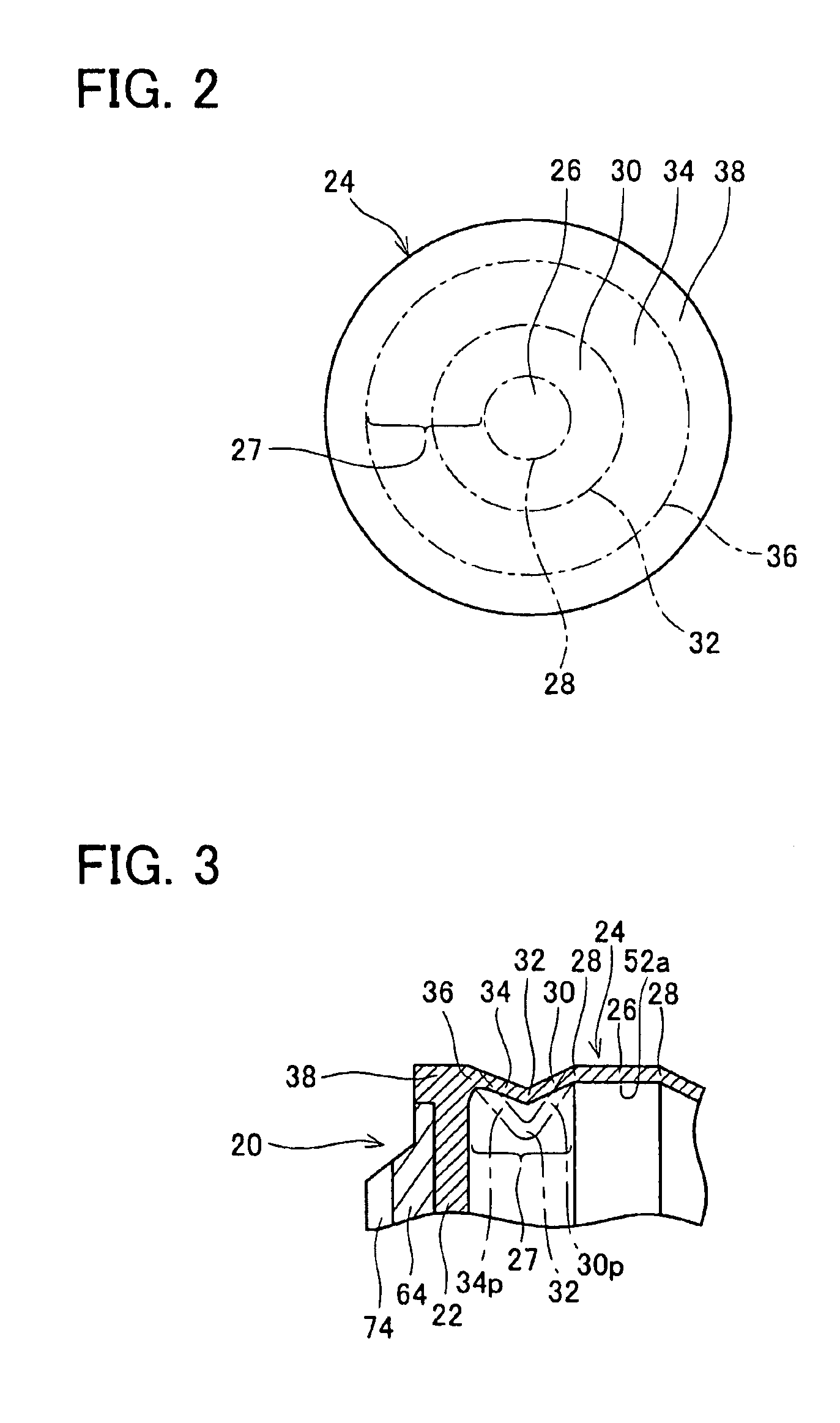
FIG. 1 shows a cross-sectional view of a pressure sensor of the present invention. The pressure sensor is provided with a housing 20, a diaphragm 24, a force transmitting rod (a force transmitting member) 52, a sensor element 54, etc. The upper side in FIG. 1 is defined as the anterior end and the lower side is defined as the posterior end. FIG. 2 shows a plan view of the diaphragm 24 of the pressure sensor, and a supporting portion 38 of the diaphragm 24. The pressure sensor is used, for example, by being attached to an engine block (not shown) of an internal combustion engine. The pressure sensor has a wide detecting range and can detect a high pressure of a combustion gas (combustion pressure) and a low pressure of an admission vacuum.

The housing 20 has an outer housing 64 and an inner housing 22. The housing 20 is formed in an approximately cylindrical shape. The axial direction of the housing 20 is the up-down direction of FIG. 1. A threading portion 74 is formed on an outer ci...

second embodiment

(Second embodiment) FIG. 5 is a cross-sectional view showing a pressure sensor of the invention. In the pressure sensor, an inner housing 22 is formed separately from a diaphragm 24 and a diaphragm supporting portion 38. The inner housing 22 is formed of metal having a thermal expansion coefficient smaller than that of the diaphragm 24. Specifically, the diaphragm 24 is made of stainless steel, as described above, whereas the inner housing 22 is made of covar. Further, the force transmitting rod 52 formed of ceramic, and the sensor element 54 made of silicon, etc. have a thermal expansion coefficient smaller than that of the stainless steel diaphragm 24.

Furthermore, it is preferred that the inner housing 22 and the force transmitting rod 52 are made of materials having an approximately identical thermal expansion coefficient. Moreover, it is preferred that the thermal expansion coefficient of the inner housing 22 and the thermal expansion coefficient of the force transmitting rod 52...

third embodiment

(Third embodiment) In a third embodiment diaphragm 24b, as shown in a cross-section in FIG. 6, folded portions 30b and 34b formed in a surrounding region 27b are formed in an inverted V-shape. The folded portions 30b and 34b are configured such that they extend from an inner edge 28b of the surrounding region 27b towards the housing 20, and are folded at a location that is further upwards than the inner edge 28b. In the cross-section, as shown in FIG. 6, the folded portions 30b and 34b are approximately symmetrical.

In other terms, the folded portions have an inner inclined portion (third region) 30b and an outer inclined portion (fourth region) 34b. The inner inclined portion 30b extends from the inner edge 28b of the surrounding region 27b towards the joint 32b between the inner inclined portion 30b and the outer inclined portion 34b, and is inclined upwardly. The outer inclined portion 34b extends from the joint 32b towards the outer edge 36b thereof, and is inclined downwardly. T...


PUM

PropertyMeasurementUnit
forceaaaaaaaaaa
pressureaaaaaaaaaa
thermal expansion coefficientaaaaaaaaaa

Abstract

A pressure sensor is realized wherein output error of sensor element can be reduced even in the case where the pressure sensor is utilized in high temperature conditions. A pressure sensor is provided with a housing 20, a diaphragm 24 that partitions the interior and the exterior of the housing 20, a sensor element 54 provided within the housing 20, output value of the sensor element 54 varying in accordance with force exerted thereupon, and a force transmitting rod 52 provided within the housing, the force transmitting rod 52 moving downwardly when a pressure is exerted upon the diaphragm 24, the force transmitting rod 52 thereby exerting force upon the sensor element 54. The diaphragm 24 has a central region 26 contacting with the force transmitting rod 52, and a surrounding region 27 surrounding the periphery of the central region 26 and connecting the central region 26 with the housing 20. The surrounding region 27, viewed cross-sectionally along the radius, is V-shaped or U-shaped, and cancels thermal expansion.

Description

CROSS-REFERENCEThe present application claims priority based on Japanese Patent Application 2003-142874 filed on May 21, 2003. The specification and figures of that Japanese application are hereby incorporated by reference as a part of the specification and figures of the present application.FIELD OF THE INVENTIONThe present invention relates to pressure sensors.BACKGROUND OF THE INVENTIONA pressure sensor is utilized to measure a pressure of various circumstances, such as a pressure of a combustion gas (combustion pressure) in an internal combustion engine.(FIRST PRIOR ART) A prior art pressure sensor shown in FIG. 13 is provided with a housing 20, a diaphragm 102, a force transmitting member 52 and a sensor element 54. The diaphragm 102 partitions an interior and an exterior of the housing 20. The force transmitting member 52 is provided within the housing 20 and moves downwardly in the figure, when a pressure at the exterior of the housing 20 is exerted upon a top surface 102a of...

Claims


Application Information

Patent Timeline
Patent Type & Authority Patents(United States)
IPC IPC(8): G01L7/02G01L7/08G01L19/04G01L23/08
CPCG01L23/18G01L23/10
Inventor MIZUNO, KENTAROTSUKADA, KOUJIOMURA, YOSHITERUHASHIMOTO, SHOJISAKATA, JIRO
Owner TOYOTA CENT RES & DEV LAB INC
Why Eureka
Try Eureka