
Illuminating apparatus

A technology for lighting devices and lighting lamps, applied in lighting devices, fixed lighting devices, lighting auxiliary devices, etc., can solve the problems of heavy operation burden and achieve the effect of easy operation

Active Publication Date: 2008-10-01
桑麦克斯株式会社
View PDF2 Cites 4 Cited by
  • Summary
  • Abstract
  • Description
  • Claims
  • Application Information

AI Technical Summary

Problems solved by technology

At the same time, it is necessary to keep the base member in the pushed-up state, and it is very burdensome to carry out this series of operations by one person.

Method used


Image

  • Illuminating apparatus
  • Illuminating apparatus
  • Illuminating apparatus

Examples


Embodiment Construction

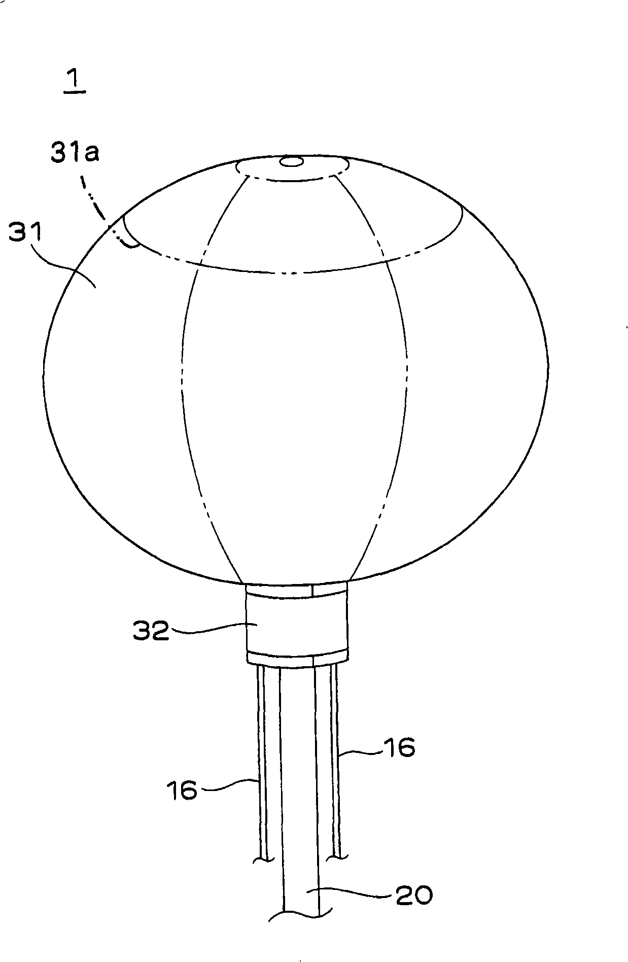
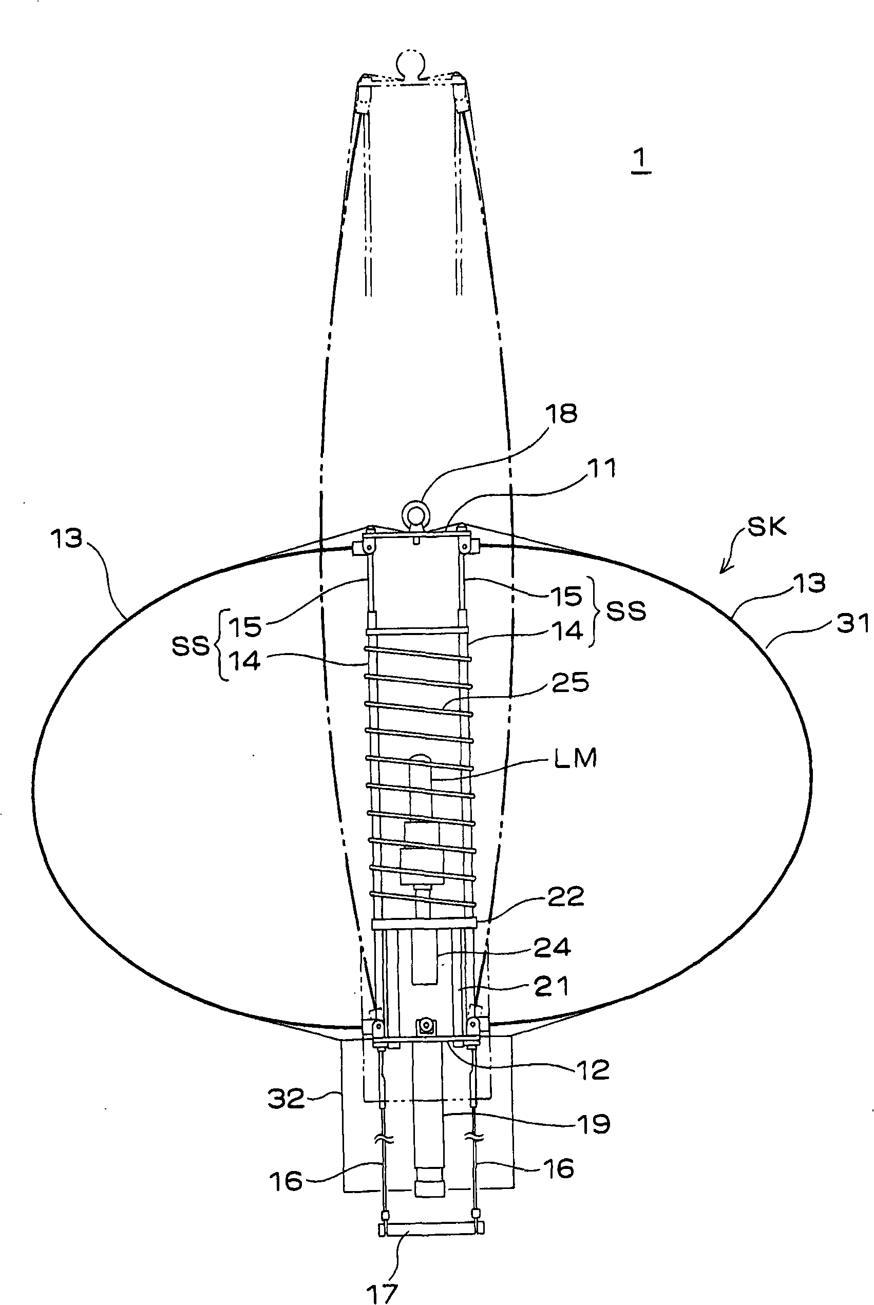
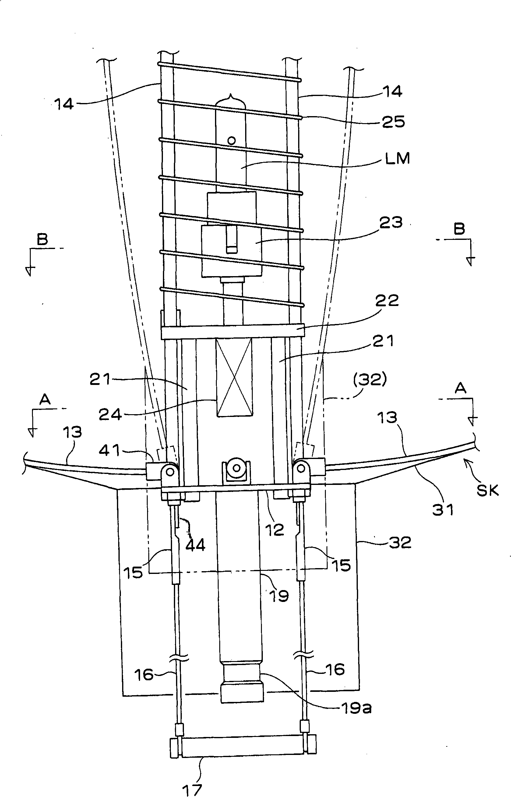
[0036] figure 1 It is a perspective view showing the appearance of the lighting device 1 of the present invention, figure 2 is a sectional front view of the lighting device 1, image 3 is enlarged figure 2 A sectioned front view of a part of Figure 4 yes image 3 A-A line to view the sectional view, Figure 5 yes image 3 B-B line to view the sectional view, Figure 6 It is an enlarged cross-sectional front view showing the connecting part of the slender stick parts, Figure 7 is a sectional front view showing the telescoping strut structure, Figure 8 yes Figure 7 Sectional right side view of the structure of the telescoping strut shown.

[0037] Such as figure 1 and figure 2 As shown, the illuminating device 1 constitutes a telescopic bone structure by arranging a plurality of flexible elongated stick members 13, 13, 13... radially between a disc-shaped top member 11 and a base member 12. SK, a balloon member 31 is provided on the outer surface of the telesc...


PUM


Abstract

A umbrella balloon type illuminator is used for the operation of the balloon swell and can not bring much burden to the operator. The illuminator has a flex bone tuberculosis body arranged radially with a plurality of flexible slim label parts (13) between a top part (11) and a bottom part (12) and a balloon part (31) arranged outside the flex bone tuberculosis body. The top part (11) and the bottom part (12) are connected through the telecopic prop composed of a pipe part (14) and a bar part (15). On the bar part (15), a stop part (44) for matching with the opening end and preventing the telecopic prop from moving to the extending direction at the protrudent part from the opening end in the constractive state of the telecopic prop.

Description

technical field [0001] The present invention relates to a lighting device used at a construction site, an accident site, or an outdoor competition venue, and particularly relates to a so-called balloon-type lighting device. Background technique [0002] Conventionally, as a balloon-type lighting device, a gas-type device in which air is blown into a balloon by a blower or a fan to inflate it has been used. However, this type of device would not be usable in the event of a balloon rupture. In addition, since the blower or the fan must be constantly operated, it cannot be used in a place where the sound of its operation becomes disturbing, for example, during filming or the like. [0003] In response to this, various umbrella-type lighting devices have been proposed, in which a balloon is inflated by expanding a long and thin stick member such as an umbrella rib. For example, in the balloon-type lighting device disclosed in Patent Document 1, a plurality of bone members comp...

Claims


Application Information

Patent Timeline
Patent Type & Authority Applications(China)
IPC IPC(8): F21S8/00F21V17/00F21V21/00
Inventor 东本正夫
Owner 桑麦克斯株式会社
Learn More