Rotator for powder conveyance and toner cartridge

A technology of toner box and rotating body, which is applied in the direction of electric recording technology using charge pattern, equipment for electric recording technology using charge pattern, and electrography, etc., which can solve the problem of the reduction of the ability of the agitator to transport the toner and the impact Problems such as toner transfer, toner volume increase, etc., to achieve the effects of small gaps, prevention of aggregation and accumulation, and reduction of powder volume

Active Publication Date: 2008-10-01
FUJIFILM BUSINESS INNOVATION CORP
View PDF2 Cites 4 Cited by
  • Summary
  • Abstract
  • Description
  • Claims
  • Application Information

AI Technical Summary

Problems solved by technology

[0008] However, a problem with this agitator is that if the transfer load applied to the agitator is reduced, the outer dimension of the agitator is reduced so that the gap between the outer peripheral surface of the agitator and the inner surface of the container becomes larger, As a result, the amount of toner left on the inner surface of the container by the agitator increases, thereby reducing the ability of the agitator to convey the toner
[0009] Also, a problem with this type of agitator is that since the agitator is formed from a thin metal wire that is simply bent into a helical configuration and is supported danglingly in the container, the agitator may be deformed longitudinally and tend to be radially Jumping; as a result, during the agitation and transfer of the toner, the agitator locally contacts the inner surface of the container, which affects the transfer of the toner and may cause the abrasion powder of the inner surface to be mixed into the toner

Method used


Image

  • Rotator for powder conveyance and toner cartridge
  • Rotator for powder conveyance and toner cartridge
  • Rotator for powder conveyance and toner cartridge

Examples


no. 1 approach

[0038] Refer below Figure 2 to Figure 5 A first exemplary embodiment of a rotary body for powder conveyance and a toner cartridge using the same according to the present invention will be described. It should be noted that the rotary body for powder conveyance and the toner cartridge using the same according to the present invention are not limited to the exemplary embodiments described below.

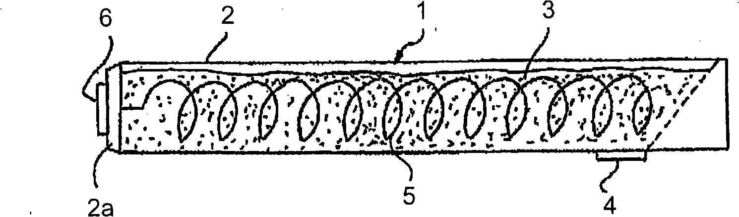
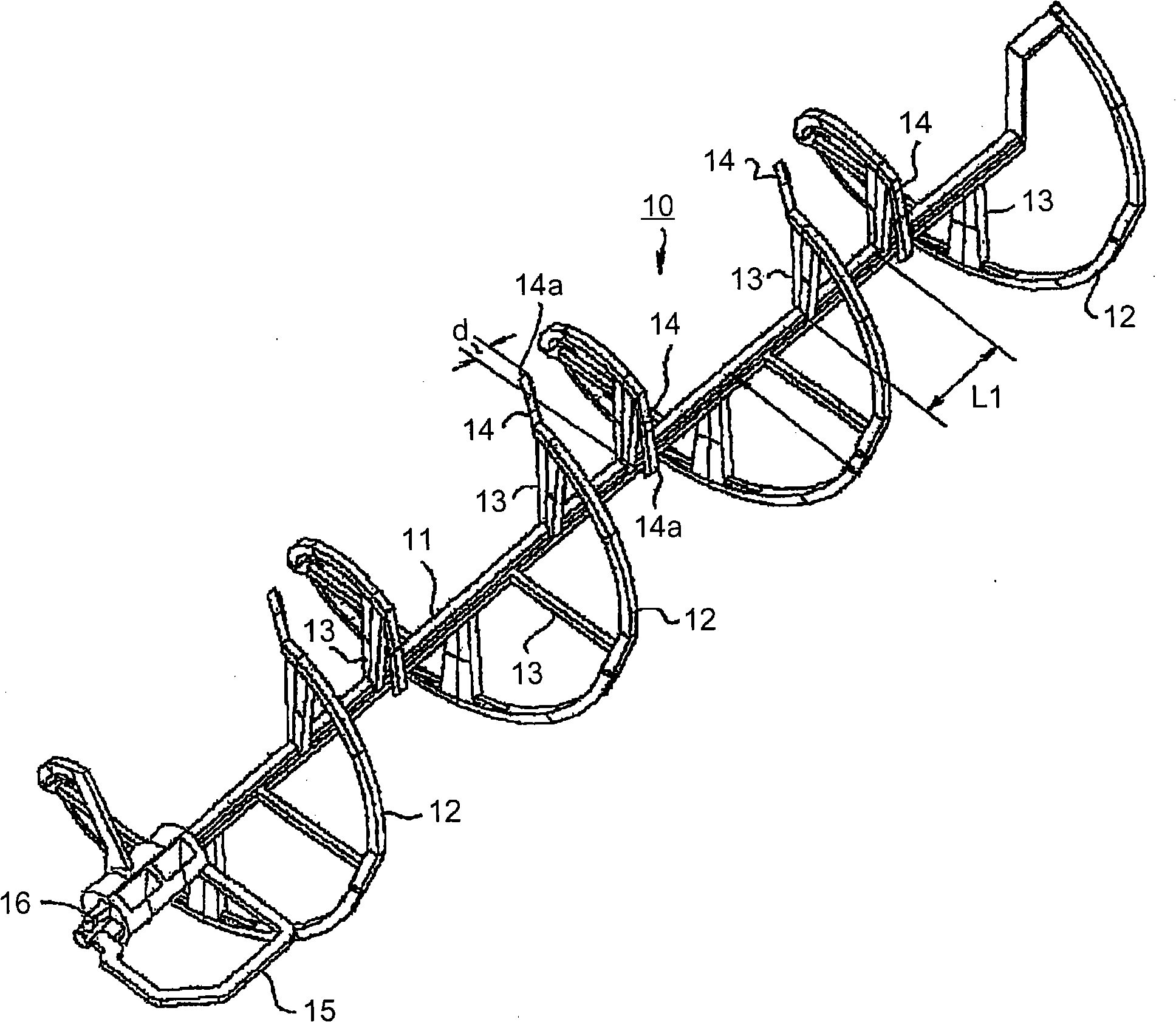
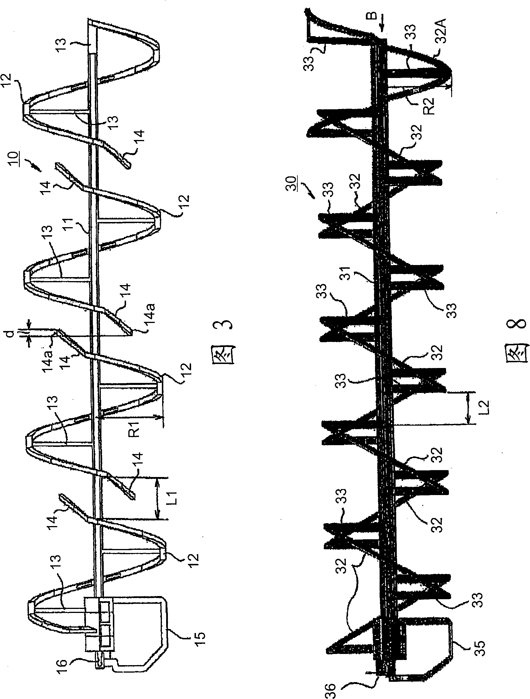
[0039] figure 2is an external view of the rotating body for powder transfer according to the first exemplary embodiment of the present invention. 3 is a plan view of a rotating body for powder transfer according to a first exemplary embodiment of the present invention. 4 is an oblique perspective view of a main body portion of a rotating body for powder transfer fixed in a container according to a first exemplary embodiment of the present invention. Figure 5 is an oblique perspective view of a toner cartridge in which the rotating body for powder conveyance according to the first...


PUM


Abstract

A rotator for powder conveyance includes a substantially linear rotary supporting shaft and plural stirring / conveying pieces. The plural stirring / conveying pieces are separated from each other and arranged in a longitudinal direction along the rotary supporting shaft, are placed at positions separated from a central axis of the rotary supporting shaft in a radial direction of the rotary supporting shaft, have a spiral configuration along an outer peripheral surface of the rotary supporting shaft, and are respectively connected to the rotary supporting shaft via a connecting piece at plural points.

Description

technical field [0001] The present invention relates to a toner cartridge used in an image forming apparatus such as an electrophotographic copier, a printer or a facsimile machine, or a complex machine, and to a device for agitating and conveying powder such as toner Rotary body for conveying powder. Background technique [0002] An image forming apparatus such as an electrophotographic copier or a printer has a toner cartridge for supplying toner used in printing an image. [0003] In such a toner cartridge, in order to smoothly supply the toner to the developing unit, it is necessary to avoid any clogging in the toner cartridge that prevents the toner from being conveyed. Therefore, an agitator (rotary body for powder conveyance) for agitating and conveying the toner is provided in the toner cartridge, and the toner accommodated in the toner cartridge is agitated by the rotation of the agitator and released. Transfer to a developing unit (for example, see JP-A-2004-8581...

Claims


Application Information

Patent Timeline
Patent Type & Authority Applications(China)
IPC IPC(8): G03G15/08
CPCG03G15/0877G03G2215/0827G03G15/0875G03G15/0839
Inventor 乘越理俊
Owner FUJIFILM BUSINESS INNOVATION CORP
Why Eureka
Try Eureka