Occupant weight measurement device for vehicle seat and installation structure for load sensor
A technology of load sensor and measuring device, which is applied in the direction of vehicle seat, special position of vehicle, measuring device, etc. It can solve the problems of assembly position error, size error, difficult assembly, etc., and achieve the effect of easy assembly
- Summary
- Abstract
- Description
- Claims
- Application Information
AI Technical Summary
Problems solved by technology
Method used
Image

Examples
Embodiment Construction
[0024] Hereinafter, the best mode for carrying out the present invention will be described with reference to the drawings. However, the embodiments described below limit various technically preferable modes for implementing the present invention, but the scope of the present invention is not limited to the following embodiments and illustrated examples.
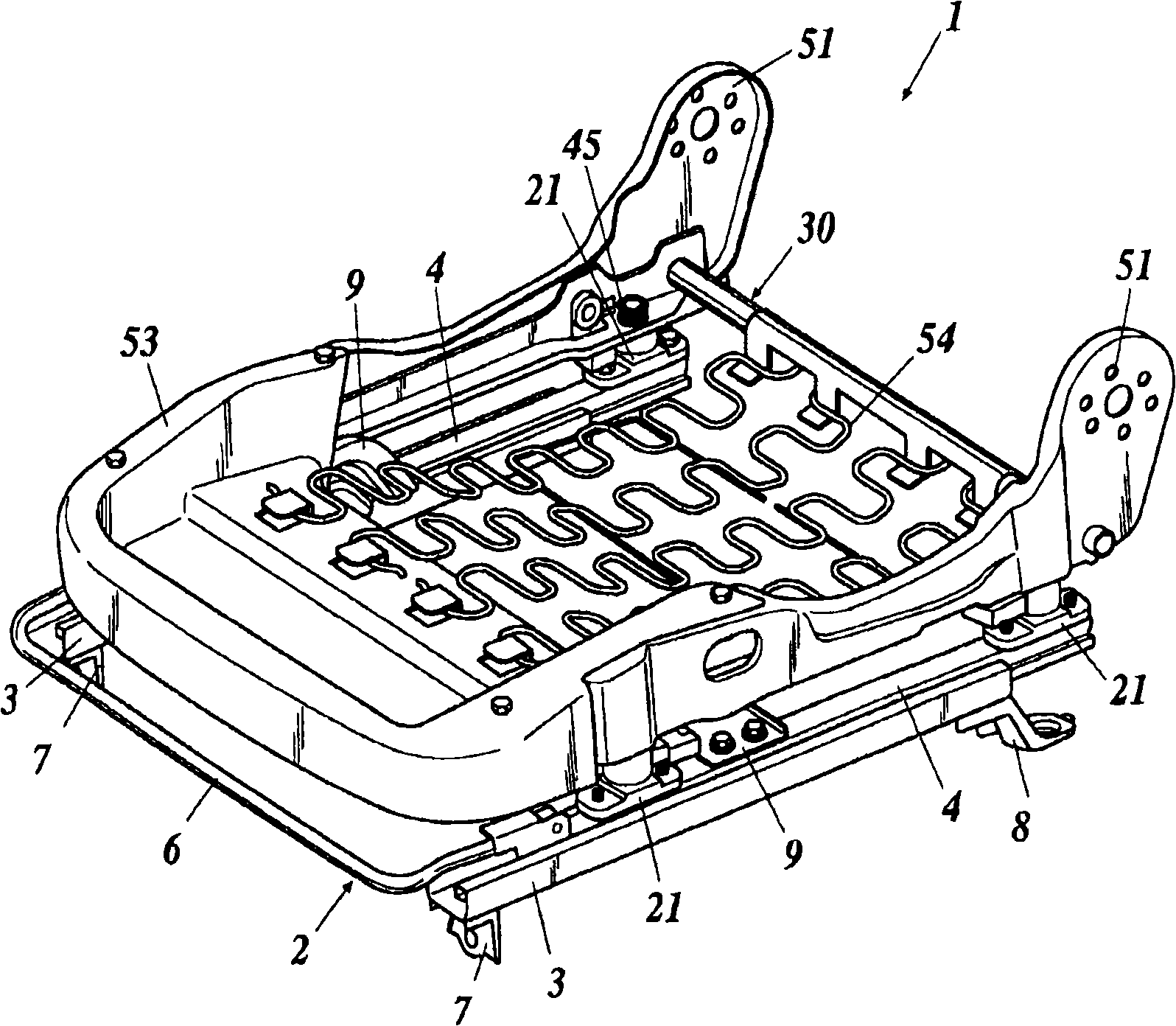
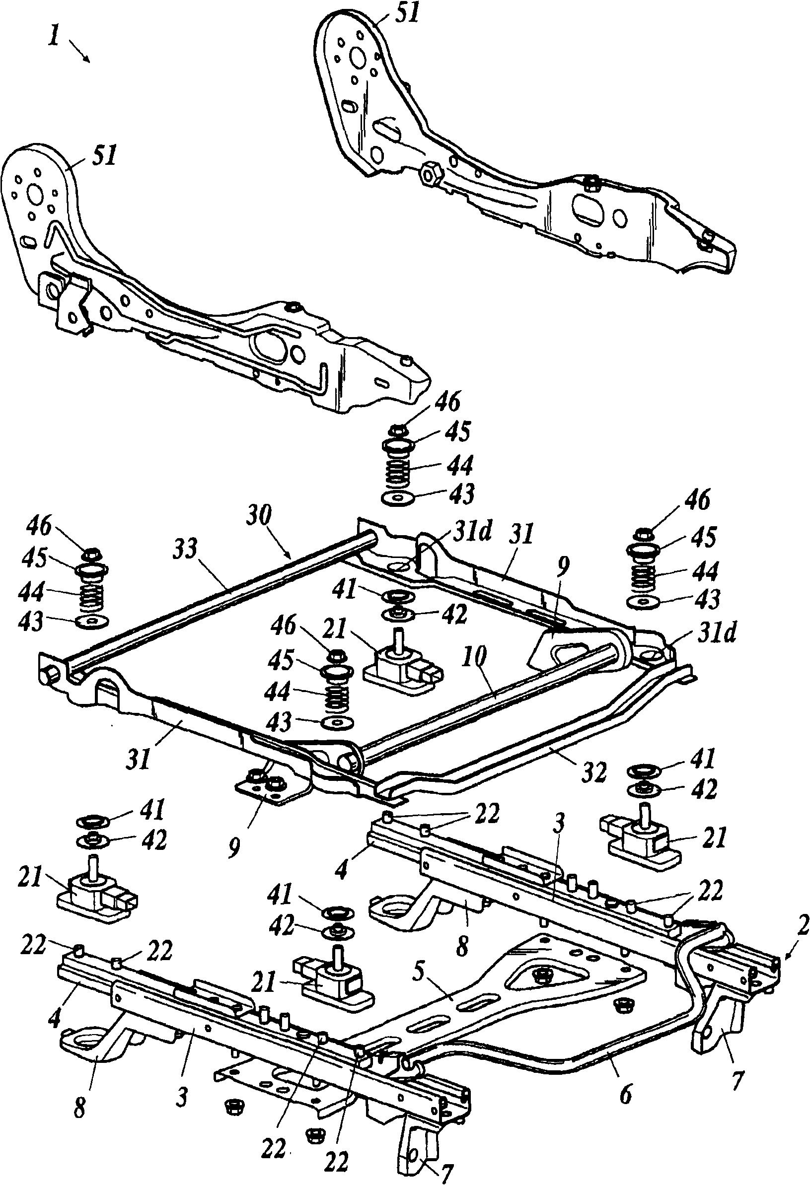
[0025] figure 1 is a perspective view of an occupant weight measuring device 1 for a vehicle seat, figure 2 It is an exploded perspective view of the occupant weight measuring device 1 .
[0026] Such as Figure 1 ~ Figure 2 As shown, a slide adjuster 2 for adjusting the front and rear positions of the vehicle seat is installed on the floor of the passenger compartment. The slide adjuster 2 includes: a pair of left and right lower rails 3 arranged in parallel to each other, and a pair of left and right upper parts that engage with the lower rails 3 so as to be slidable on the lower rails 3 in the front-rear direction rela...
PUM
 Abstract
Description
Claims
Application Information
 - R&D
- Intellectual Property
- Life Sciences
- Materials
- Tech Scout
- Unparalleled Data Quality
- Higher Quality Content
- 60% Fewer Hallucinations
Browse by: Latest US Patents, China's latest patents, Technical Efficacy Thesaurus, Application Domain, Technology Topic, Popular Technical Reports.
© 2025 PatSnap. All rights reserved.Legal|Privacy policy|Modern Slavery Act Transparency Statement|Sitemap|About US| Contact US: help@patsnap.com