Optical disk drive and tracking error detection method for an optical disk drive

A technology of optical disc drive and tracking error, which is applied in the direction of recording/reproducing with optical methods, instruments, optical record carriers, etc., and can solve the problems of inapplicability, unreliable signal, disappearance, etc.

Inactive Publication Date: 2008-10-01
KONINKLIJKE PHILIPS ELECTRONICS NV
View PDF2 Cites 0 Cited by
  • Summary
  • Abstract
  • Description
  • Claims
  • Application Information

AI Technical Summary

Problems solved by technology

[0014] Additionally, for the broad spiral principle, new methods or structures need to be invented to embed timing and addressing information into (re)writable format discs, because when the track pitch within the broad spiral is close to the optical cutoff or even falls within Below that, any signal from the push-pull channel carried by the wobble structure embedded in the groove of the disc becomes unreliable or even disappears
For individual tracks, the wobble concept does not apply

Method used


Image

  • Optical disk drive and tracking error detection method for an optical disk drive
  • Optical disk drive and tracking error detection method for an optical disk drive
  • Optical disk drive and tracking error detection method for an optical disk drive

Examples


Embodiment Construction

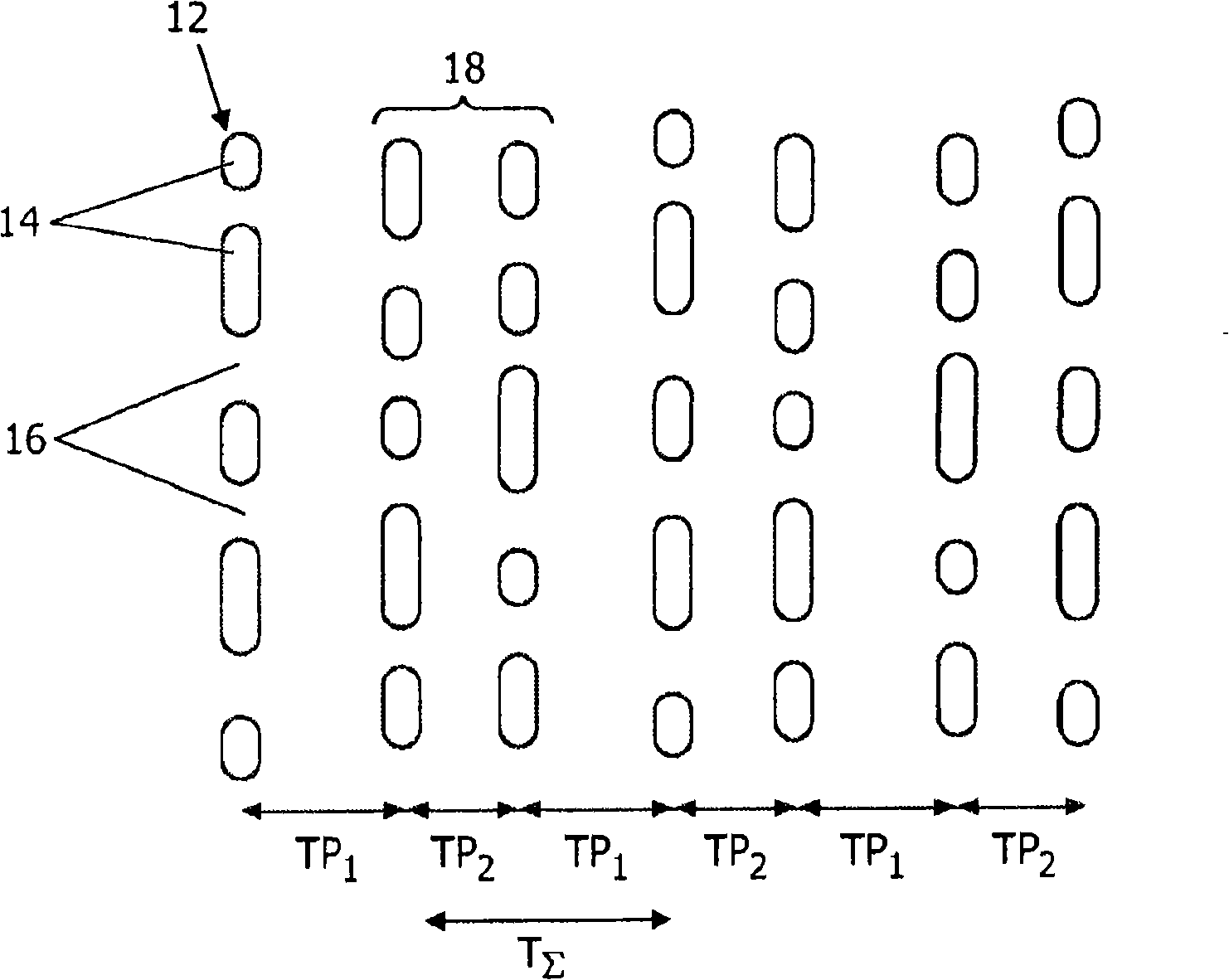
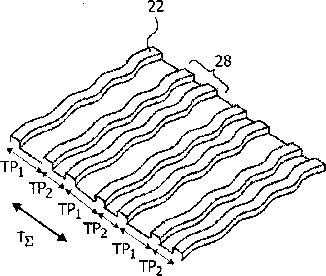
[0033] figure 1 The portion of the new disk shown represents the disk in read-only format. A track portion 12 therein is constituted by trajectories formed by pits 14 and lands 16 . likewise in figure 2 , a perspective view of a portion 20 of a (re)writable disc is shown, where the track portion is formed by a wobbled pre-groove 22 . Such pre-grooves for tracking purposes in non-written optical discs are known, for example, from the CD-R / RW, DVD±R / RW or BD-R / RF standards, among others.

[0034] On both formats, tangential tracks of pits and lands in the read-only format and pre-grooves in the (re)writable format, the track portions 12, 22 are not equally spaced. Select two different track pitches TP 1 and TP 2 , so that every second track portion is set to the left from its adjacent track portion by the first distance TP 1 and a second distance TP at the right margin to its adjacent track portion 2 . In this way, beams 18 and 28 are formed, respectively, consisting of...


PUM


Abstract

The present invention relates to a tracking error detection method for an optical storage system wherein an optical disk comprises a plurality of adjacent track portions with a radial track pattern in which a number n>2 of adjacent track portions repeatedly exhibit non-uniform radial track distances (TP1<>TP2 . . . <>TPn), whereby the sum of said radial track distances (TPSigma=TP1+ . . . +TPn) is higher than the reciprocal optical cutoff lambda / ( 2 NA) of the optical disk drive. The method comprises projecting a plurality of (n) satellite light spots (S1, . . . , Sn; SL, SM) and one main spot (SR) onto said optical disk, each satellite spot being displaced in radial direction off the main spot by another one of half the radial track distances (TP1 / 2<>TP1 / 2<> . . . <>TPn / 2), respectively, and generating push-pull signals (PP1, . . . ,PPn; PPL, PPM) for each satellite spot. The invention further relates to an optical disk drive implementing said method.

Description

technical field [0001] The invention relates to an optical disc drive comprising a beam generator arranged to project a plurality of satellite spots and a main spot onto an optical disc, and a tracking error detection device comprising an arrangement arranged to detect light reflected from the optical disc An array of photodetectors and at least one push-pull signal generator coupled to the array of detectors and arranged to generate push-pull signals. [0002] The invention also relates to a tracking error detection method for an optical storage system comprising such an optical disc drive and an optical disc. Background technique [0003] In an optical disc system comprising an optical storage disc and an optical disc drive, the effective diameter Φ=λ / (2NA) of the light spot produced by the pickup unit (PUU) of the disc drive (which inversely corresponds to the highest spatial frequency or the so-called light cutoff (optical cutoff) 2NA / λ) determines the radial and tangen...

Claims


Application Information

Patent Timeline
IPC IPC(8): G11B7/007G11B7/085G11B7/09G11B7/24079
CPCG11B7/0943G11B7/24079G11B7/08505G11B7/08529G11B7/0903G11B7/085G11B7/09
Inventor B·殷
Owner KONINKLIJKE PHILIPS ELECTRONICS NV
Why Eureka
Try Eureka