Trajectory tracking flight controller

a flight controller and trajectory technology, applied in adaptive control, navigation instruments, instruments, etc., can solve the problems of difficult stability testing of complex control structures, slow time-varying and benign, and significant technical challenges for tracking on guided munitions and missile systems in particular

Active Publication Date: 2012-04-19
OHIO UNIV
View PDF6 Cites 51 Cited by
  • Summary
  • Abstract
  • Description
  • Claims
  • Application Information

AI Technical Summary

Benefits of technology

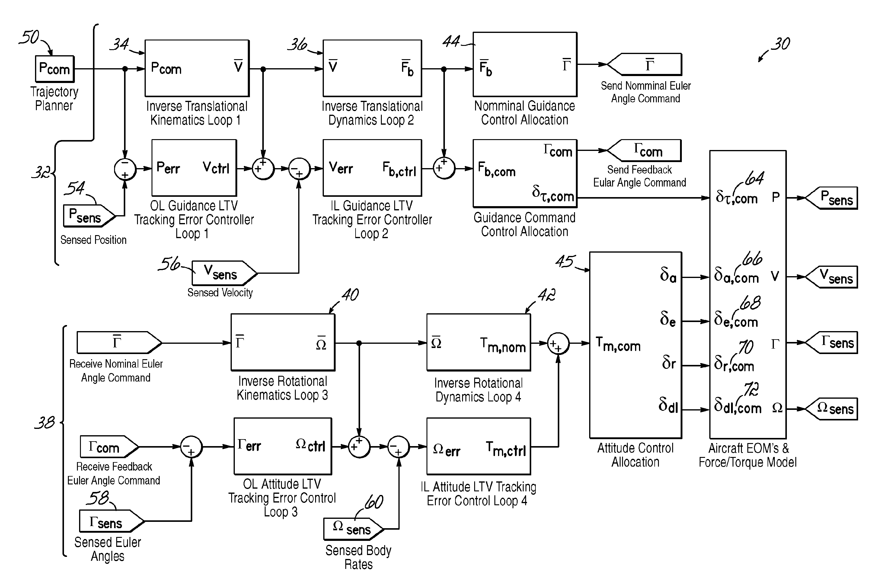
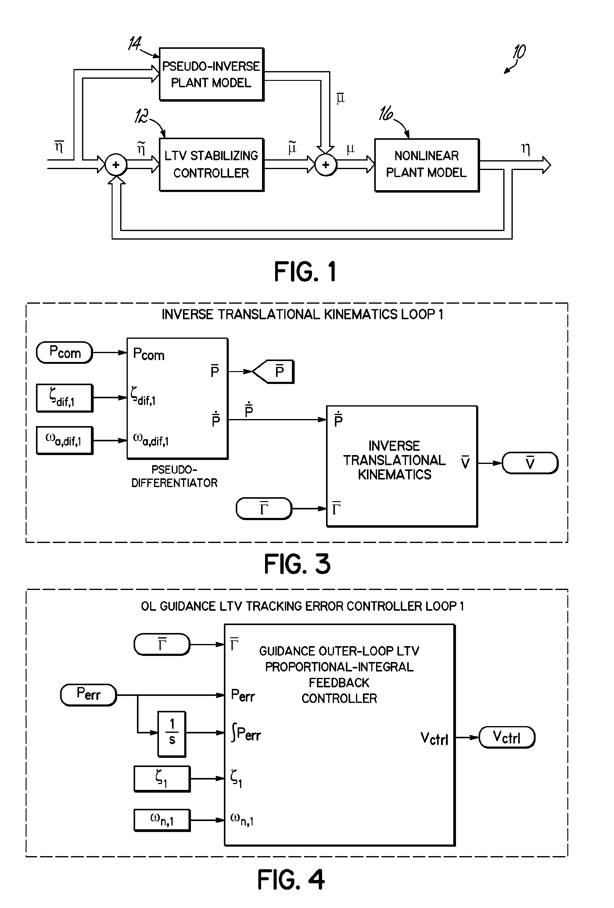
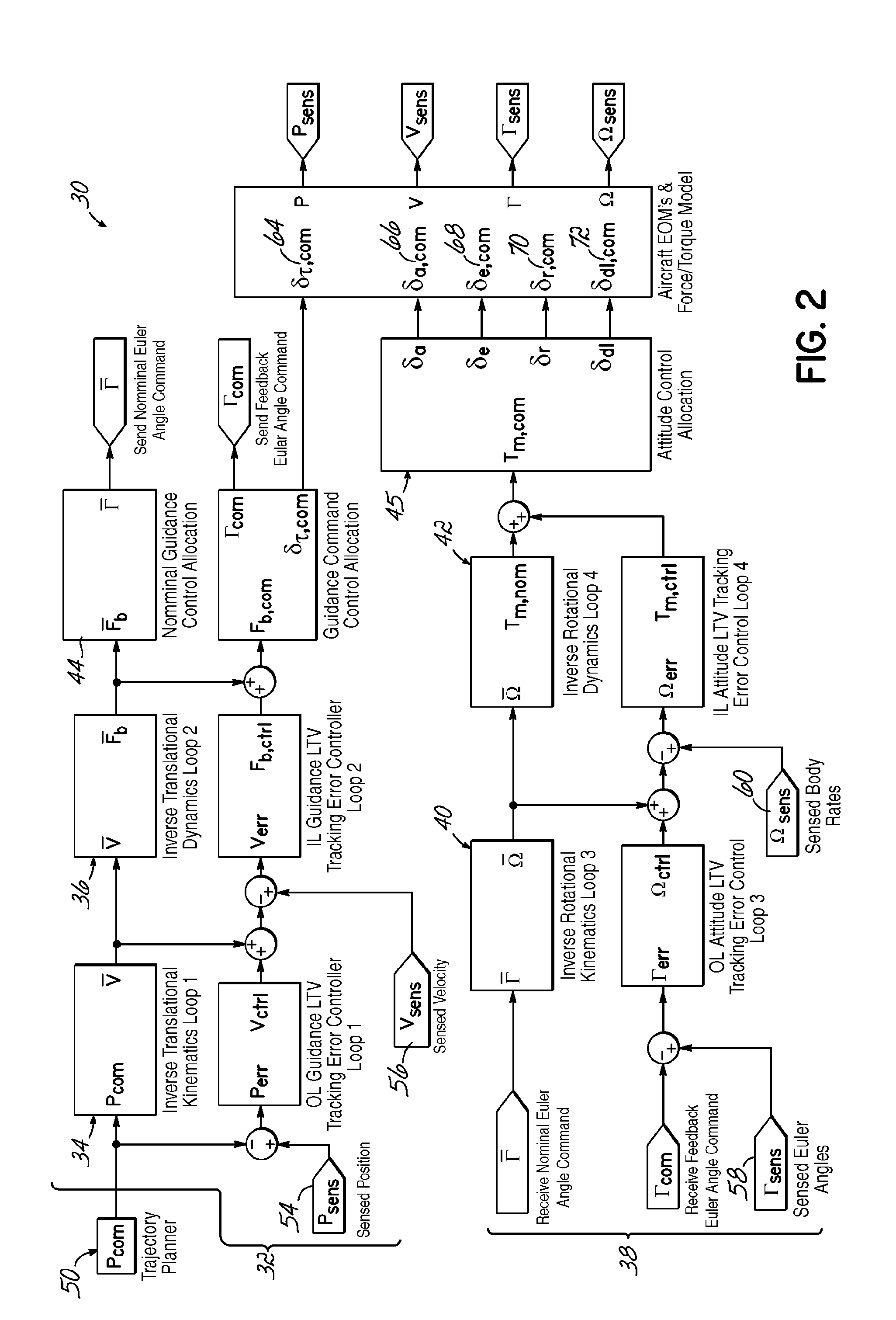
[0008]The TLC architecture includes a processor and program code configured to execute on the processor to generate the control signal by determining in a first control loop a nominal body velocity vector and a feedback control body velocity command vector using the command position vector from the trajectory planner; determining in a second control loop a nominal Euler angle vector, a feedback control Euler angle command vector, and a throttle setting feedback control command using the nominal body velocity vector and the feedback control body velocity command vector from the first control loop; determining in a third control loop a nominal body rate vector and a feedback control body rate command vector using the nominal Euler angle vector and the feedback control Euler angle command vector from the second control loop; determining in a fourth control loop a moment command vector using the nominal body rate vector and the feedback control body rate command vector from the third control loop; and determining the control signal using the moment command vector from the fourth control loop.
[0009]In another aspect of this embodiment, the control signal is further generated by determining in the first control loop the feedback control body velocity command vector further uses a sensed position vector from the avionic sensor, determining in the second control loop the feedback control Euler angle command vector and the throttle setting feedback control command further uses a sensed velocity vector from the avionic sensor, determining in the third control loop the nominal body rate vector and the feedback control body rate command vector further uses a sensed Euler angle vector from the avionic sensor, determining in the fourth control loop the moment command vector further uses a sensed body rate vector from the avionic sensor.
[0010]The control signal includes an engine throttle, aileron, elevator, rudder, or a direct lift (such as a flaperon) deflection command. The aircraft may include an airframe and a control effector, where the control effector is adapted to receive the control signal from the control actuator. The control effector is an engine throttle, aileron, elevator, rudder, or flaperon.
[0011]The invention also contemplates a method of generating a control signal, the method comprising determining using a hardware implemented processor in a first control loop a nominal body velocity vector and a feedback control body velocity command vector using a command position vector for a fixed-wing aircraft from a trajectory planner; determining using the processor in a second control loop a nominal Euler angle vector, a feedback control Euler angle command vector, and a throttle setting feedback control command using the nominal body velocity vector and the feedback control body velocity command vector from the first control loop; determining using the processor in a third control loop a nominal body rate vector and a feedback control body rate command vector using the nominal Euler angle vector and the feedback control Euler angle command vector from the second control loop; determining using the processor in a fourth control loop a moment command vector using the nominal body rate vector and the feedback control body rate command vector from the third control loop; and determining using the processor a control signal using the moment command vector from the fourth control loop.
[0012]The method may also generate the control signal based in part on sensed parameters from an avionics sensor. Thus, the generating the control signal may involve determining in the first control loop the feedback control body velocity command vector further uses a sensed position vector from the avionics sensor, determining in the second control loop the feedback control Euler angle command vector and the throttle setting feedback control command further uses a sensed velocity vector from the avionic sensor, determining in the third control loop the nominal body rate vector and the feedback control body rate command vector further uses a sensed Euler angle vector from the avionic sensor, determining in the fourth control loop the moment command vector further uses a sensed body rate vector from the avionic sensor.
[0013]The invention also contemplates a program product comprising a computer readable medium and program code stored on the computer readable medium, the program code configured to execute on a hardware implemented processor to generate a control signal by determining in a first control loop a nominal body velocity vector and a feedback control body velocity command vector using the command position vector from a trajectory planner; determining in a second control loop a nominal Euler angle vector, a feedback control Euler angle command vector, and a throttle setting feedback control command using the nominal body velocity vector and the feedback control body velocity command vector from the first control loop; determining in a third control loop a nominal body rate vector and a feedback control body rate command vector using the nominal Euler angle vector and the feedback control Euler angle command vector from the second control loop; determining in a fourth control loop a moment command vector using the nominal body rate vector and the feedback control body rate command vector from the third control loop; and determining the control signal using the moment command vector from the fourth control loop.

Problems solved by technology

Tracking on guided munitions and missile systems in particular poses significant technical challenges because of inherent uncertainties, nonlinearity of the systems, and demanding performance requirements for tracking highly maneuverable targets.
A backstepping controller has been compared to a classical nonlinear dynamic inversion control approach for a path angle trajectory controller, where model selection was found to impact performance of the inversion control, but the backstepping approach led to a complex control structure that was difficult to test with limited guarantee of stability.
Gain-scheduling controllers suffer from inherent slowly-time-varying and benign nonlinearity constraints, and the controller design and tuning are highly trajectory dependent.
A drawback of this type of control scheme is that the nonlinearity cancellation is accomplished in the LTI control loop.
Consequently, imperfect cancellation because of sensor dynamics or modeling errors result in nonlinear dynamics that are not compensated for by the LTI controller design, and cannot be effectively accommodated by the LTI controller.

Method used


Image

  • Trajectory tracking flight controller
  • Trajectory tracking flight controller
  • Trajectory tracking flight controller

Examples


verification example

F. Design Verification Example

[0134]The TLC architecture 30 described in Section D was verified using the Matlab / SIMULINK software using the full nonlinear equations of motion, Equations (3), (10), (26), and (31), and the aerodynamic force / moment model given in Section C. The state vector was given by

X=[xE yE zE u v w φθψ p q r]T,  (39)

and each of the three control surfaces (aileron, elevator, and rudder) and the constant speed propeller were implemented with actuator dynamics given as G(s)=10 / (s+10).

[0135]As described above, each of the four control loops shown in the FIG. 2 are constructed similarly and include a dynamic pseudo-inverse plant model and an LTV tracking error controller. As a specific example, the outer-loop guidance controller, as described FIG. 3, shows the contents of the block labeled “Inverse Translational Kinematics Loop 1” from FIG. 2. The inertial position state integrators are initialized in this block, and a three-channel pseudo-differentiator is provided f...


PUM


Abstract

A six degree-of-freedom trajectory linearization controller (TLC) architecture (30) for a fixed-wing aircraft (46) is set forth. The TLC architecture (30) calculates nominal force and moment commands by dynamic inversion of the nonlinear equations of motion. A linear time-varying (LTV) tracking error regulator provides exponential stability of the tracking error dynamics and robustness to model uncertainty and error. The basic control loop includes a closed-loop, LTV stabilizing controller (12), a pseudo-inverse plant model (14), and a nonlinear plant model(16). Four of the basic control loops (34, 36, 40, 42) are nested to form the TLC architecture (30).

Description

FIELD OF THE INVENTION[0001]The invention relates generally to a trajectory tracking controller for a fixed-wing aircraft.BACKGROUND OF THE INVENTION[0002]Trajectory tracking control has been studied extensively and applied to wide range of platforms, including small unmanned vehicles, helicopters, transport-class aircraft in the context of next-generation air transport, and resilient aircraft control. Tracking on guided munitions and missile systems in particular poses significant technical challenges because of inherent uncertainties, nonlinearity of the systems, and demanding performance requirements for tracking highly maneuverable targets.[0003]Gain scheduling has been used for trajectory tracking of autonomous vehicles, though gain-scheduling approaches are often used ad-hoc in the design. Trajectory Linearization Control (TLC) has been described as including consisting of a nonlinear, dynamic pseudo-inversion based open-loop nominal controller, together with a linear, time-va...

Claims


Application Information

Patent Timeline
Patent Type & Authority Applications(United States)
IPC IPC(8): G05D1/00G05B13/02
CPCG05D1/101G05D1/0825G05D1/0808G05D1/08G01C21/12G01C21/20G05D1/085
Inventor ZHU, JIANCHAOADAMI, TONY M.
Owner OHIO UNIV
Why Eureka
Try Eureka