Technique for producing arcuated combined flue pipe

A production process and air duct technology, which is applied in the field of the production process of arc-shaped combined air ducts, can solve the problems of affecting the ventilation effect, inconvenient use and installation, air duct airflow obstruction, etc., so as to ensure the cooling and heating effect, and the installation is convenient and simple. , to avoid the effect of airflow obstruction

Inactive Publication Date: 2011-09-14
支亮
View PDF0 Cites 0 Cited by
  • Summary
  • Abstract
  • Description
  • Claims
  • Application Information

AI Technical Summary

Problems solved by technology

When the ventilation ducts to be manufactured are curved ducts, three-ventilation ducts, and four-ventilation ducts, if the existing hard straight ducts are used, a deep bend will be formed at the corners, and the airflow in the ducts will be easily ventilated at the corners. Bring obstacles, affect the ventilation effect, and bring inconvenience to use and installation

Method used


Image

  • Technique for producing arcuated combined flue pipe
  • Technique for producing arcuated combined flue pipe
  • Technique for producing arcuated combined flue pipe

Examples


Embodiment 1

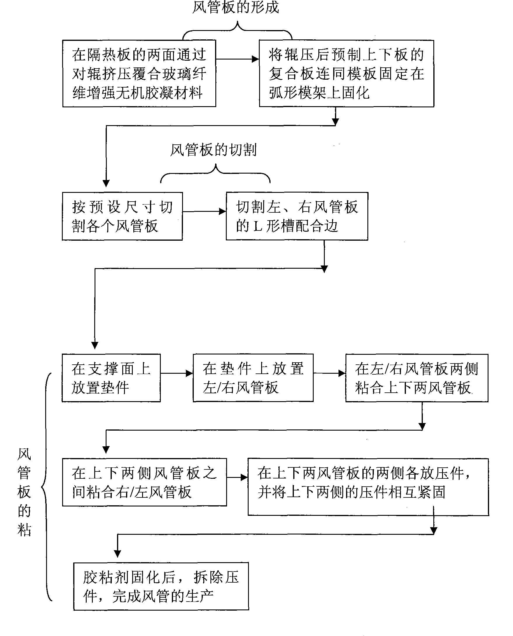
[0021] Embodiment 1: A manufacturing process of a curved combined air duct, such as figure 1 As shown, the steps of the process are: step one, making of the air duct plate; step two, cutting of the air duct plate; step three, bonding of the air duct plate, and the manufacturing process of the air duct plate is: a. Roll one layer of fiber-reinforced inorganic viscose layer 1 on the template, then place the selected heat insulation board 2 on the fiber-reinforced inorganic viscose layer 1, and then roll a layer of fiber-reinforced inorganic viscose on the upper surface of the heat insulation board 2. Adhesive layer 1, forming a composite board (such as image 3 shown); b, the composite boards of the prefabricated left and right air duct panels are placed flat and solidified; c, after the composite panels of the prefabricated upper and lower air duct panels 5 are bent into an arc together with the formwork, they are fixed on the curved concave Solidification and setting on the s...

Embodiment 2

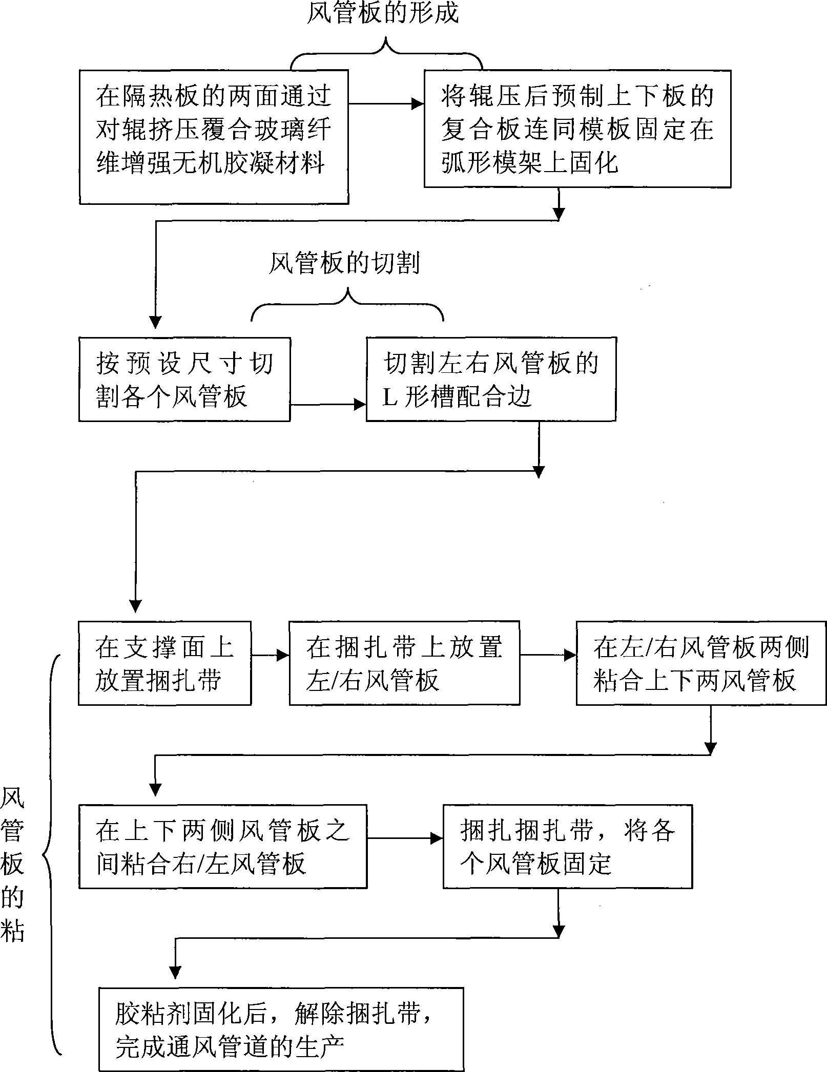
[0024] Embodiment 2: A kind of manufacturing process of curved combined air duct, such as figure 2 and Figure 8 As shown, the bonding process of the air duct plate included in the process is: A, first place a plurality of straps 9 evenly on the bearing surface, and place the left and right air duct plates 4 on the straps 9; B , the upper and lower air duct plates 5 are bonded to both sides of the left and right air duct plates, then the left and right air duct plates 4 are bonded between the two air duct plates; C, the binding strap 9. Bundling along the transverse direction of each air duct plate; D. After the adhesive is cured, remove the above-mentioned binding belt 9. All the other steps are the same as in Example 1.


PUM


Abstract

The invention relates to a process for making an arc combined air duct, which includes the following steps of: 1. making a duct plate; 2. cutting the duct plate; 3. bonding the duct plate. The duct plate includes the following manufacturing working procedures that: a, a fiber reinforced inorganic viscose layer is rolled on a template, then a selected thermal baffle is arranged on the fiber reinforced inorganic viscose layer, and then a fiber reinforced inorganic viscose layer is rolled on the upper surface of the thermal baffle so as to form a composite plate; b, the composite plate for prefabricating a left duct plate and a right duct plate is placed flat, solidified and shaped; c, the composite plate for prefabricating an upper duct plate and a lower right duct plate, and the template are bent to take an arc shape and then fixed on a setting device with arc grooves for solidification and shaping. The process for making the arc combined air duct has the advantages that the air duct manufactured by adopting the process can be conveniently applied to a ventilating duct with elbows, three ways or four ways to keep the ventilating duct smooth and fluent and avoid the internal airflow from being blocked so as to effectively reduce the noise and ensure the using effect, and can be simply and conveniently arranged.

Description

【Technical field】 [0001] The invention relates to a process for manufacturing ventilation ducts used in the field of construction or air conditioning, and in particular to a process for manufacturing arc-shaped combined air ducts in which each air duct plate is arc-shaped. 【Background technique】 [0002] The combined air duct is based on the foam board (such as polyethylene foam board, rubber-plastic foam board) as the carrier, and the glass fiber inorganic cementitious material is composited on the two sides of the foam board to make the air duct board, and then the air duct boards are combined. Form ventilation ducts. After the inorganic gelling material is solidified, the prepared air duct plate is a hard flat plate, which cannot be bent, and the air duct prepared by using the existing manufacturing process is a straight pipe type. When the ventilation ducts to be manufactured are curved ducts, three-ventilation ducts, and four-ventilation ducts, if the existing hard str...

Claims


Application Information

Patent Timeline
Patent Type & Authority Patents(China)
IPC IPC(8): B29D23/00B32B37/15B29C65/48E04F17/04F16L9/00
CPCF24F13/0281F24F13/0245F24F13/0272
Inventor 支亮
Owner 支亮
Why Eureka
Try Eureka