Longitudinal feeding structure of electronic pattern sewing machine

A pattern sewing machine and longitudinal feeding technology, which is applied in the field of sewing machines, can solve problems such as waste of labor and clothing materials, incorrect patterns or patterns, and tilting of the cloth pressing device

Inactive Publication Date: 2008-10-08
JACK SEWING MASCH CO LTD
View PDF0 Cites 7 Cited by
  • Summary
  • Abstract
  • Description
  • Claims
  • Application Information

AI Technical Summary

Problems solved by technology

At present, the longitudinal mechanism of electronic pattern sewing machines is generally driven by a single arm. Due to the instability of the single arm structure, it is easy to cause the cloth pressing device to tilt during the formation of the pattern or pattern, or the cloth pressing device on one side is not tight. As a result, the pattern or p

Method used


Image

  • Longitudinal feeding structure of electronic pattern sewing machine
  • Longitudinal feeding structure of electronic pattern sewing machine

Examples


Embodiment Construction

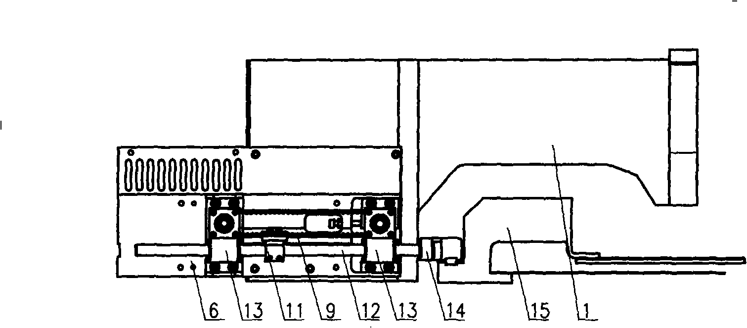
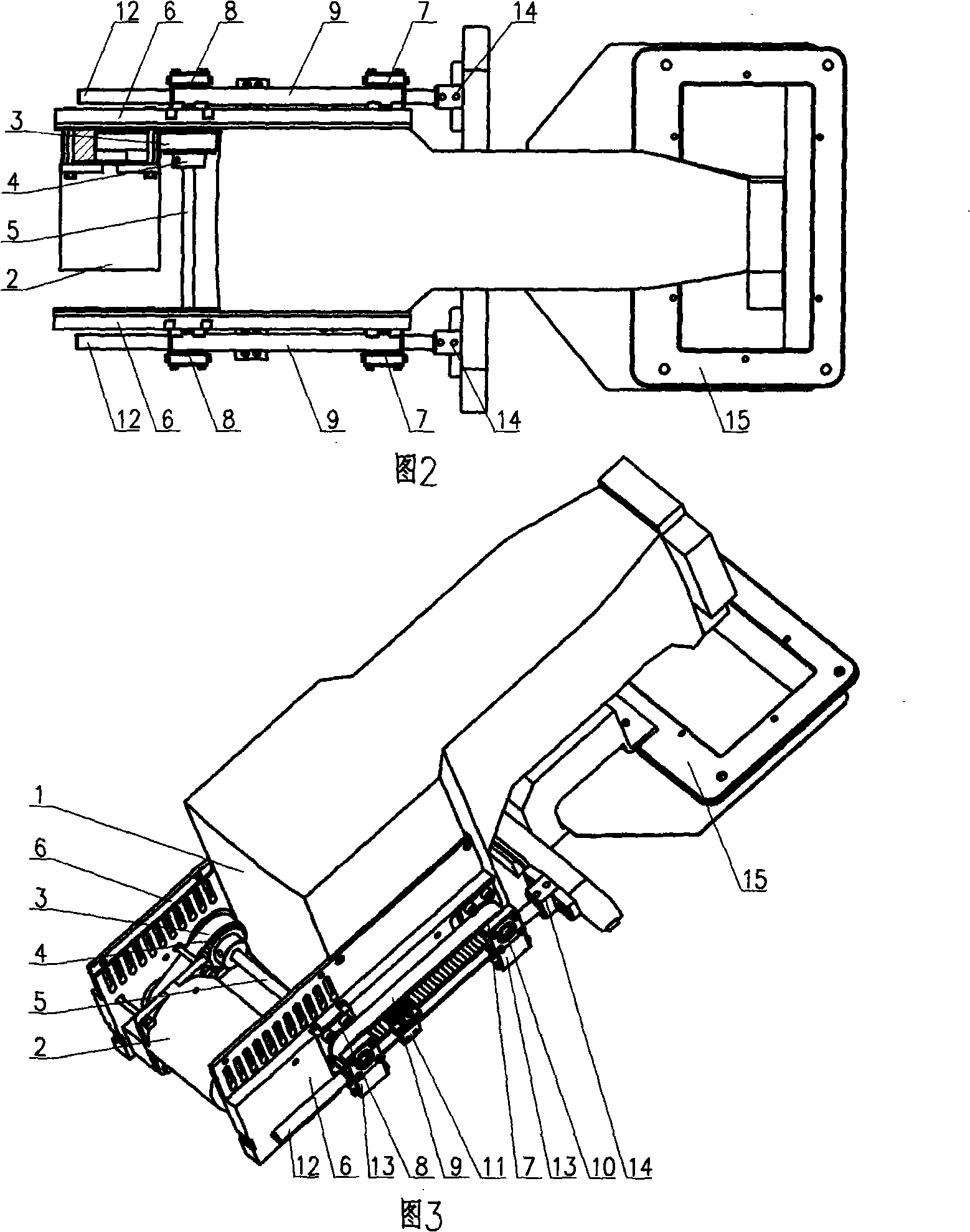
[0009] refer to figure 1 , Fig. 2 and Fig. 3, the cloth pressing device 15 and the feed shaft 12 are connected together through the connection assembly 14, the feed shaft 12 pushes the cloth pressing device 15 to realize longitudinal feeding, and the feed shaft 12 is separately installed in the machine head 1 On the feed shaft holders 13 on both sides, the feed shaft holders 13 are fixed on the fixed bracket 6 with screws respectively. At this time, the fixed bracket 6 is installed on the machine head 1 with screws, and the power of the feed shaft 12 It is provided by the feed synchronous belt 9. At this time, the feed shaft 12 and the feed synchronous belt 9 are connected together by the feed shaft and the synchronous belt clamping assembly 11, and the feed synchronous belt 9 is fed through the active synchronous pulley 7 to drive. The feeding active synchronous pulley 7 is installed at both ends of the synchronous pulley shaft 5, through the synchronous pulley 4 installed o...


PUM


Abstract

The invention belongs to the sewing machine technology, in particular to the design of a vertical feed mechanism of an electronic pattern machine that a holding apparatus can be driven to move stably, which comprises a nose1, a motor 2, a synchronous motor drive belt 3, a synchronous pulley 4, a synchronous pulley shaft 5, a fixation apparatus 6, a feed drive synchronous pulley 7, a feed driven synchronous pulley 8, a feed synchronous belt 9, a feed driven synchronous belt shaft 10, a feed shaft and a synchronous belt clamping component 11, a feed shaft 12, a feed shaft fixation seat 13, a connection component 14 and a holding apparatus 15, and characterized in that the vertical feed power of the holding apparatus 13 of the electric pattern machine is provided from the motor 1 through twice transmission of the synchronous belt and can be controlled through the program. The vertical feed of the holding apparatus 15 is achieved through the pushing of the feed shaft 12 in fractional packed on the fixation seat 13 of feed shaft on both sides of the nose. The power of the feed shaft 12 is provided through the feed synchronous belt 9. The feed shaft 12 and the feed synchronous belt 9 are linked together through the feed shaft and the synchronous clamping component 11. The power of the motor 2 is connected through a synchronous structure, thus the vertical feed of the electric pattern machine is achieved.

Description

Technical field: [0001] The invention belongs to the sewing machine technology, and in particular designs a structure capable of stably driving the longitudinal feed of an electronic pattern machine. Background technique: [0002] Due to the development of the garment industry, the market's demand for patterns or patterns on clothing is becoming more and more extensive, which requires sewing machines that can quickly form patterns or patterns on clothing, which requires us to speed up the improvement of electronic pattern sewing machines. to increase efficiency. Electronic pattern sewing machine is a high-end type of sewing machine. It uses the vertical and horizontal feeding structure to drive the cloth pressing device of the machine, so as to drive the movement of the cloth, and then uses the stitch formation principle of the sewing machine to form various patterns on the cloth. the goal of. At present, the longitudinal mechanism of electronic pattern sewing machines is ...

Claims


Application Information

Patent Timeline
IPC IPC(8): D05B69/10D05B35/00D05B9/00D05B21/00
Inventor 李创陈健蔡敏华
Owner JACK SEWING MASCH CO LTD
Why Eureka
Try Eureka