Weights of standard machine loading device

The technology of a loading device and a standard machine, applied in the field of weights, can solve the problems such as the inability of the torque to stabilize, the influence of the accuracy of the indication value, and the influence of the detection efficiency, and achieve the effects of novel structure, accurate weight quality and stable unloading process.

Inactive Publication Date: 2008-10-08
CHONGQING CONSTR ELECTROMECHANICAL CO LTD
View PDF1 Cites 3 Cited by
  • Summary
  • Abstract
  • Description
  • Claims
  • Application Information

AI Technical Summary

Problems solved by technology

However, since this kind of weight is connected by a live pin, there is a large gap between the live pin and the small hole of the weight. When unloading, the live pin cannot make the serially connected weights stably fixed, resulting in the weight not being reset accurately. Offset is prone to occur, that is, there is a misalignment between the upper weight and the lower weight. When the weight is loaded again for verification, the suspended weight will swing, causing the torque indication value to be unable to stabilize in a short time, and the indication value is accurate. In this way, the torque value of the standard machine, especially the repeatability of the small torque value, is greatly affected. Therefore, it is necessary to wait for the weight to stop swinging when using it, which seriously affects the detection efficiency and is extremely inconvenient to use.
Since the repeatability index of the indication value in the verification regulations of the national torque standard machine is less than a few ten-thousandths, the weight of the above-mentioned existing structure is used as the force loading device on the 1000N.m torque standard machine, and its actual repeatability index is 3×10 -4 ~7×10 -4 range, the repeatability index of the indication value is only ten thousand, and it is not convenient to use

Method used


Image

  • Weights of standard machine loading device
  • Weights of standard machine loading device
  • Weights of standard machine loading device

Examples


Embodiment Construction

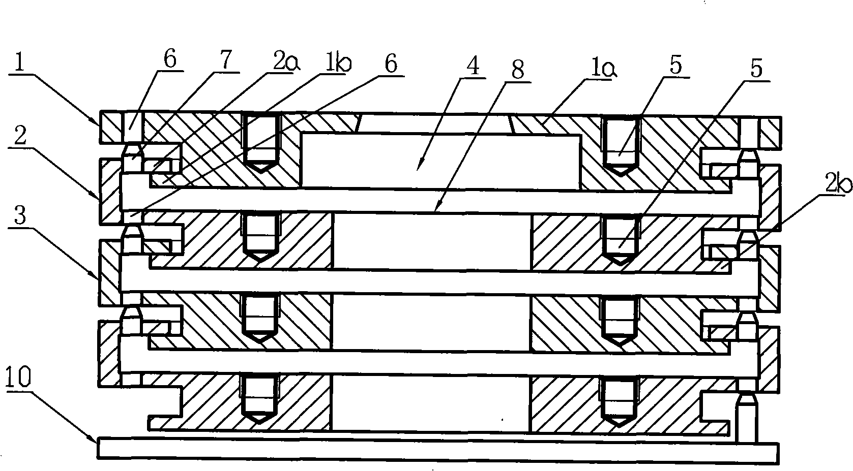
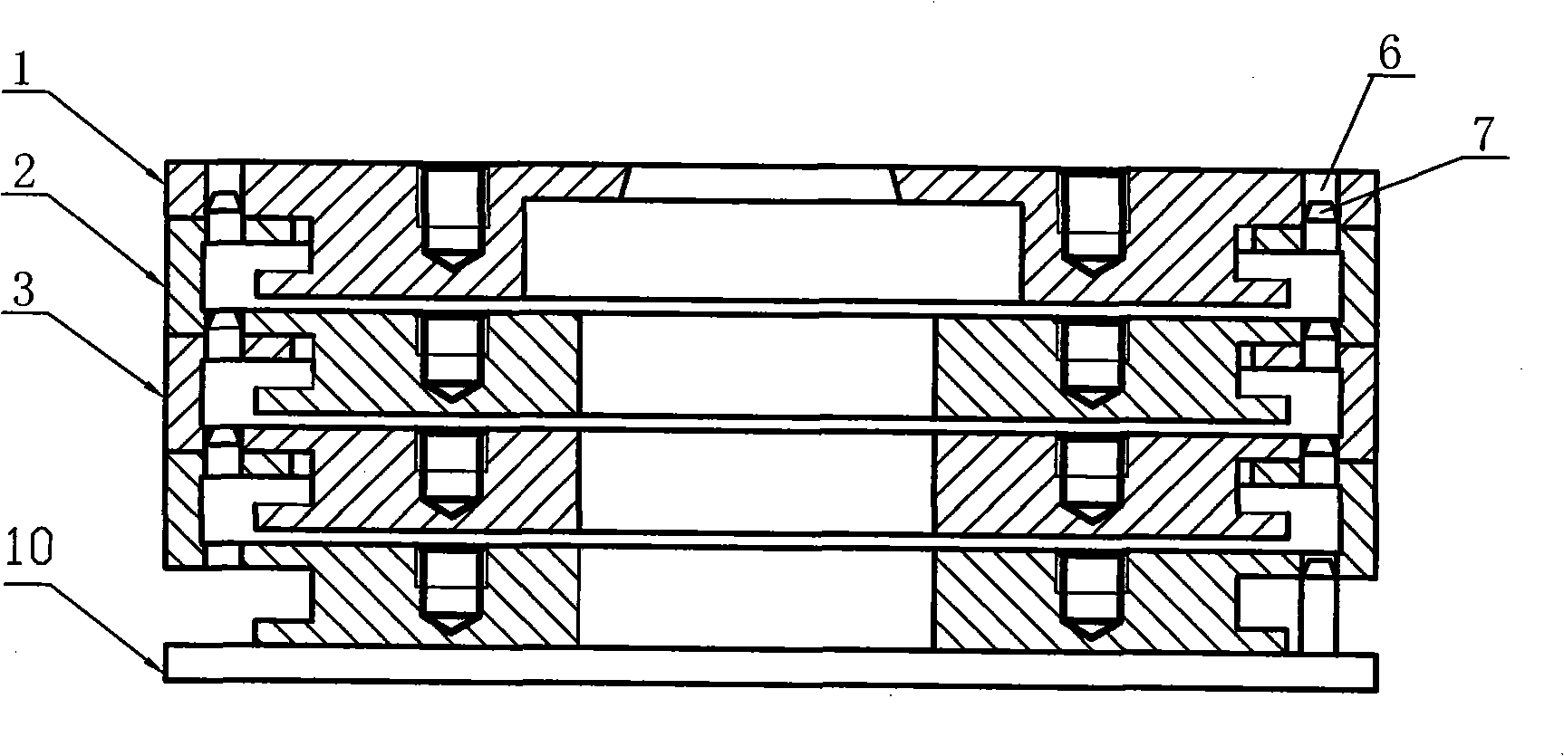
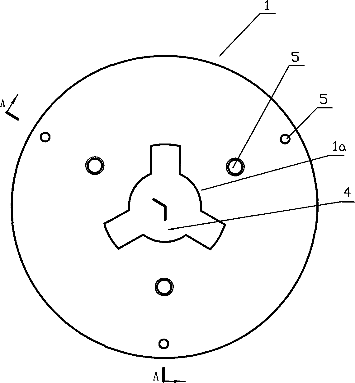
[0017] see Figure 1 to Figure 8 , is a kind of embodiment of weight of the present invention, and weight group comprises a plurality of standard value weights, is usually ten weights for a weight group, (the weight shown in the accompanying drawing only draws four for the sake of simplicity weights). Each weight of the weight group is a stepped cylinder with a through hole in the center of the circle. The upper part of the stepped cylinder is a large diameter section, and the lower part is a small diameter section. The diameters of the large diameter sections of the stepped cylinders of each weight are the same, and the small diameter The segments have the same diameter. At least three outwardly extending flanges are evenly distributed on the bottom circumference of the small diameter section of each weight. In this embodiment, the number of outwardly extending flanges is three, and the three flanges are arranged at intervals to form a socket bottom stop. The upper port of ...


PUM


Abstract

The present invention discloses a weight of standard machine loading device which comprises weight groups comprising a plurality of weights; each weight is step cylinder with circle center via; bottom circumference of small diameter section of each weight is evenly distributed with several lower spigots extending outwardly; the upper port of the first weight is evenly distributed with several upper spigots extending to the circle center; the circle center via of each weight from the second weight is step hole; the upper port at the big diameter end of the step hole is evenly distributed with several upper spigots extending to the circle center; the upper end face at the big diameter section of each weight from the second weight is evenly equipped with locating pins; the big diameter section of each weight from the first weight is further equipped with locating hole; the locating pins and locating holes of the adjacent weights are corresponding; the big diameter section of the lower weight is sleeved with the small diameter section of the upper weight in turn through the spigot. The weight is able to avoid the mutual dislocation of the upper and lower weights in the loading or unloading process, prevent the weight from swinging after loading and affect the indicating value of torque or force so as to improve the repeatability of the indicating valve.

Description

technical field [0001] The invention relates to a weight, in particular to a weight of a standard machine loading device. Background technique [0002] In industrial production, it is often necessary to use torque measuring instruments and dynamometers to measure the torque, force and other indicators of manufactured products, while torque measuring instruments and dynamometers need to be calibrated with standard force weights on the standard machine to ensure their The value is accurate and reliable. see Figure 9 , the standard force value weight of the loading device of the existing standard machine is composed of a plurality of weights, each weight is a cylindrical structure with a central through hole, and each weight is evenly distributed with four axial Pin holes 12, the adjacent upper and lower weights are respectively inserted into the pin holes by four live pins 11 and connected in series to form a weight group, the weight group is held by the tray 9 of the loadin...

Claims


Application Information

Patent Timeline
Patent Type & Authority Applications(China)
IPC IPC(8): G01L25/00
Inventor 周兆丰曹久大聂荣军叶锦成
Owner CHONGQING CONSTR ELECTROMECHANICAL CO LTD
Why Eureka
Try Eureka