Location grid with long direction eddy generator
A longitudinal vortex generator and spacer grid technology, applied in the field of spacer grids, can solve the problems of increased channel pressure drop, increased fluid resistance, etc., and achieve the effect of increasing heat transfer capacity and improving comprehensive heat transfer capacity.
- Summary
- Abstract
- Description
- Claims
- Application Information
AI Technical Summary
Problems solved by technology
Method used
Image

Examples
Embodiment Construction
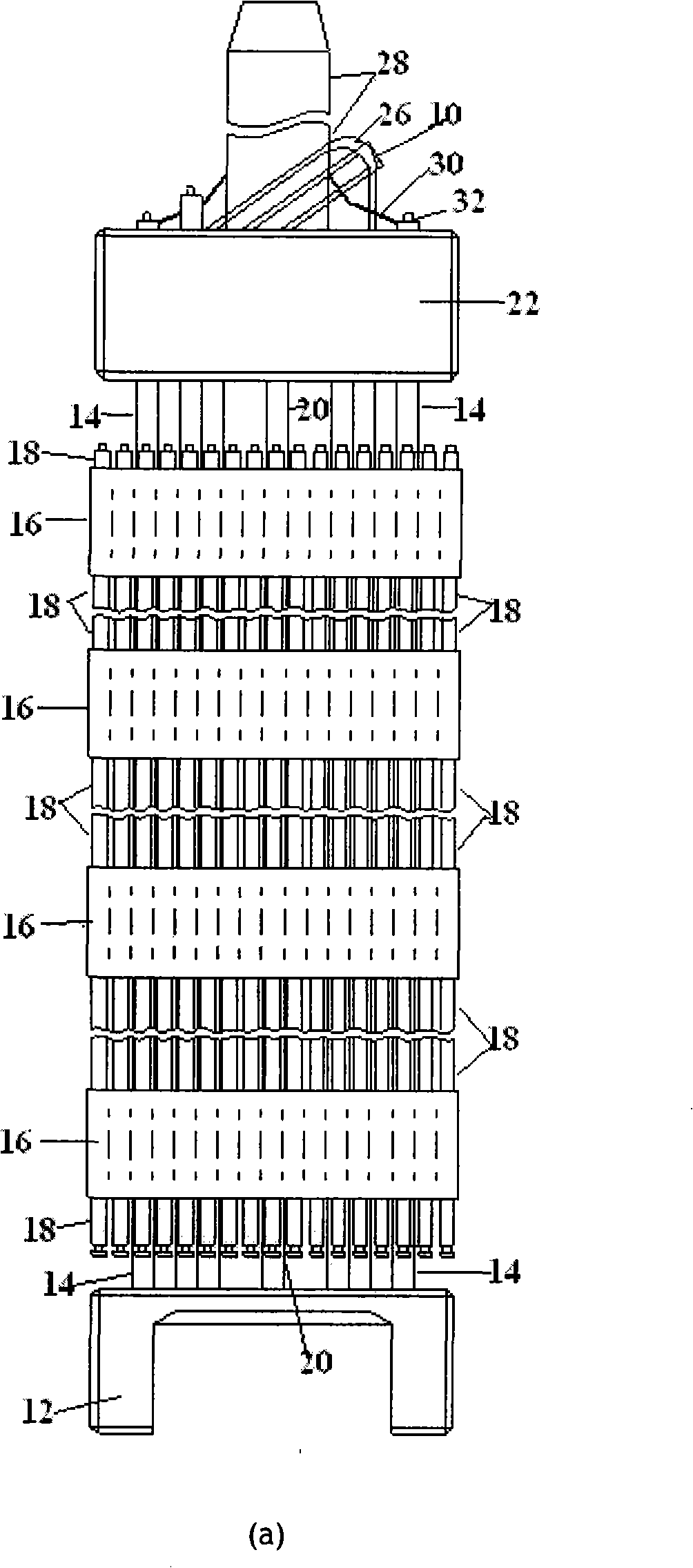
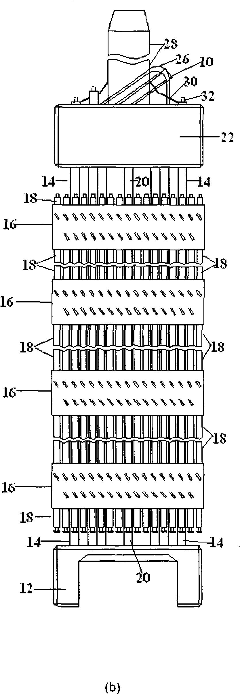
[0030] refer to figure 1 (a) and figure 1 As shown in (b), the fuel assembly 10 is made up of the lower structure or the lower nozzle base 12, the control rod guide tube 14, the spacer grid 16, the fuel rods 18, the representative tube 20 and the upper structure or the upper nozzle base 22. The lower tube base 12 is used to support the components seated on the lower core plate (not shown) of the core (not shown); the control rod guide tube 14 extends upward from the lower tube base 12; the transverse spacer The frame 16 is used to provide lateral support for the fuel rods arranged in a certain way, and the upper tube base 22 is connected to the upper end of the guide pipe 14 to form a complete assembly to perform conventional operations without damaging the fuel assembly components. Both the lower tube base 12 and the upper tube base 22 have a connecting plate, and holes are opened on the plate for liquid coolant (eg, water) to flow therethrough. In place within the box defi...
PUM
 Abstract
Description
Claims
Application Information
PatSnap Eureka turns technology decisions into work you can execute. Powered by our Innovation Knowledge Graph, it runs expert workflows across engineering, life sciences, materials and intellectual property. Get your review-ready output in minutes.


