Residual current devices

A technology of residual current and equipment, applied in the direction of measuring current/voltage, electrical components, circuit devices, etc., can solve problems such as insensitivity

Inactive Publication Date: 2008-10-08
EATON ELECTRIC INC
View PDF0 Cites 9 Cited by
  • Summary
  • Abstract
  • Description
  • Claims
  • Application Information

AI Technical Summary

Problems solved by technology

Third, it does not take into account any standing residual current already present in the circuit
When this occurs and the device is subsequently reset, the insensitivity caused by the residual magnetism means that the device can be restarted while the power circuit is still faulty

Method used


Image

  • Residual current devices
  • Residual current devices
  • Residual current devices

Examples


Embodiment Construction

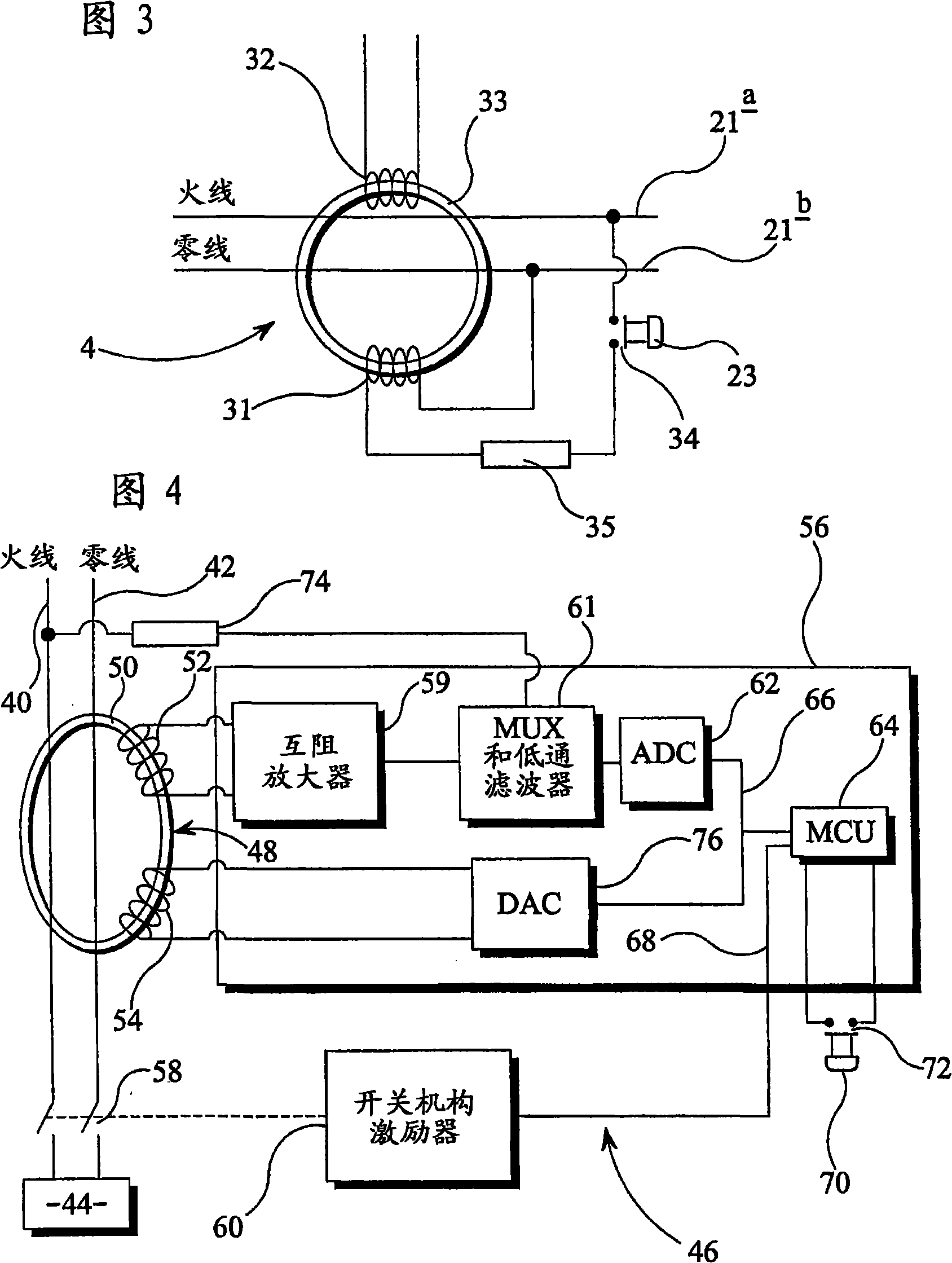
[0035] Referring to FIG. 4 , the power supply device has a live wire 40 and a neutral wire 42 for supplying current from the power source to a load circuit 44 . The RCD 46 includes a toroidal transformer 48 having a magnetic core 50 surrounding the live and neutral wires 40 , 42 . An induction coil 52 and a test coil 54 are wound on the magnetic core 50 . The current induced in induction coil 52 is provided as input to electronic processor 56 . The switching mechanism 58, which is energized by the actuator 60 under the control of the processor 56, disconnects the live and neutral wires 40, 42 when a predetermined level of residual current is detected.

[0036] In electronic processor 56, an input current flows from induction coil 52 to transimpedance amplifier 59, which has a voltage output linearly related to the input current. The output voltage of the transimpedance amplifier 59 is then injected into an analog-to-digital converter (ADC) 62 via a low-pass filter 61 (to pre...


PUM


Abstract

In one aspect, the invention provides a residual current device (RCD) for protecting a circuit by tripping in response to an imbalance signal representative of residual current imbalance in the circuit. The RCD trips the circuit when the imbalance signal exceeds a predetermined threshold rating. The RCD comprises test means for increasing the imbalance signal so as to test operation of the RCD against the rating. In another aspect the RCD comprises: a current transformer for generating an imbalance sense current in a sense coil in response to a current imbalance in an electrical supply; and a degaussing coil for substantially removing remanence in the current transformer by application of a degaussing signal to the degaussing coil.

Description

technical field [0001] The invention relates to residual current devices (RCDs). More specifically, the present invention relates to RCDs having a test device which, when energized, causes the device to trip. Background technique [0002] RCDs are installed to prevent certain potentially dangerous situations in power equipment. Such as figure 1 As shown, the power supply device 10 has some wires 11 (typically, a neutral wire and a live wire for a single-phase AC power supply, and three live wires or three live wires plus a neutral wire for a three-phase AC power supply.) The wires 11 are connected to the load A circuit 12 is connected (for example, a household loop with household appliances connected). The known RCD 13 disconnects the power supply from the load circuit 12 when an imbalance is detected in the current flowing in the conductor 11 . This imbalance is due to current flowing into ground, indicating poor insulation or someone getting electrocuted. [0003] The...

Claims


Application Information

Patent Timeline
Patent Type & Authority Applications(China)
IPC IPC(8): H02H3/32H02H3/02H01H83/14H01H71/74H02H3/33
CPCH02H3/335H02H3/334G01R19/10
Inventor J·K·杰克逊A·威廉姆斯
Owner EATON ELECTRIC INC
Why Eureka
Try Eureka