Source electrode driven inverse-excitation converting circuit

A technology of flyback conversion and source drive, which is applied in the direction of output power conversion device, conversion of DC power input to DC power output, electrical components, etc., which can solve the problem that the turn-on loss of the first switch MOS transistor Q1 cannot be controlled, and the energy Loss, circuit efficiency reduction and other issues, to achieve the effect of suppressing sudden short-term peaks, smooth transition of on-off process, and reducing turn-on loss

Active Publication Date: 2008-10-08
MORNSUN GUANGZHOU SCI & TECH
View PDF0 Cites 46 Cited by
  • Summary
  • Abstract
  • Description
  • Claims
  • Application Information

AI Technical Summary

Problems solved by technology

Since the power in the leakage inductance of the transformer T1 at the moment of turning off can only be released through the absorbing circuit, that is, through the second diode D2, it enters the third resistor R3 and the third capacitor C3 of the RC network, and is consumed on the third resistor R3, resulting in a certain energy loss, making the circuit less efficient
like figure 2 As shown, since there is no protection measure for the Miller effect when the first switch MOS transistor Q1 is turned on, a short-term peak will appear on the current of the first switch MOS transistor Q1 when it is turned on, and at this time the first switch MOS transistor Q1 The turn-on loss is not controlled

Method used


Image

  • Source electrode driven inverse-excitation converting circuit
  • Source electrode driven inverse-excitation converting circuit
  • Source electrode driven inverse-excitation converting circuit

Examples


Embodiment 1

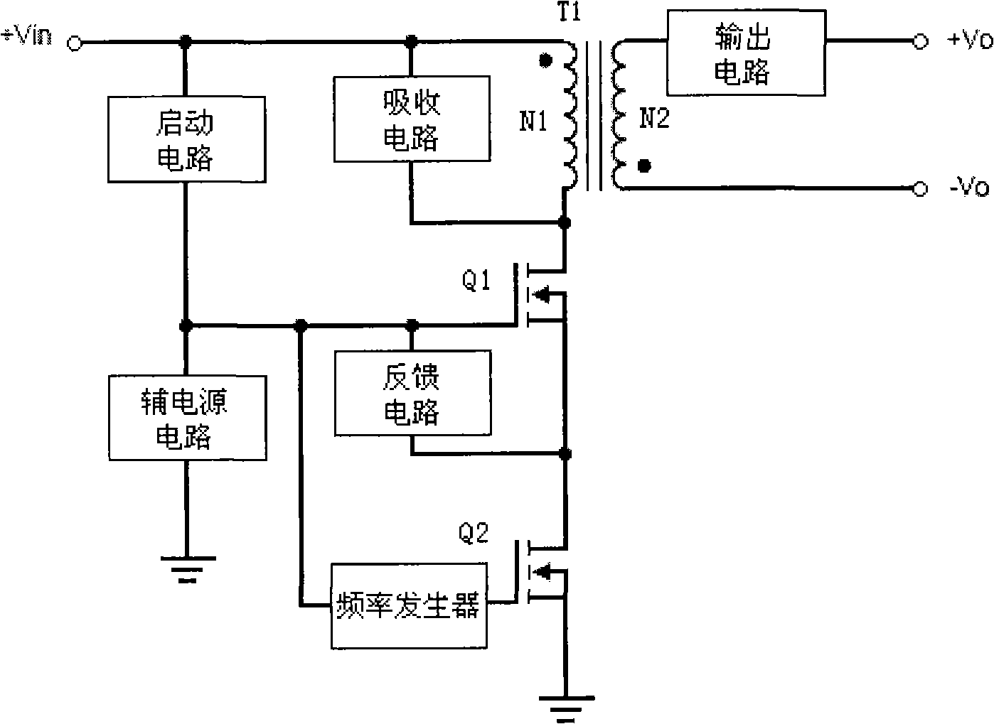
[0029] Such as image 3 , Figure 4 As shown, the present invention adopts the following scheme to achieve the above object: a source-driven flyback conversion circuit, including: a start-up circuit, an absorption circuit, a transformer T1, a first switch MOS transistor Q1, a frequency generator and an output circuit, and the input power Divided into three ways to connect: the first way is connected to the same-named end of the primary winding N1 of the transformer T1, connected to the drain of the first switch MOS transistor Q1 through the different-named end of the primary winding N1 of the transformer T1, and connected in series through the source of the first switch MOS transistor Q1 The drain of the second switch MOS transistor Q2 is grounded through the source of the second switch MOS transistor Q2; the second path is connected to the different terminal of the transformer T1 and the drain of the first switch MOS transistor Q1 after passing through the absorption circuit;...

Embodiment 2

[0041] Such as Image 6 As shown, the difference compared with Embodiment 1 is that a fifth capacitor C5 is connected in parallel to both ends of the source and drain of the first switch MOS transistor Q1, and the function is to sense the second capacitor C2 of the auxiliary power supply through the leakage of the primary winding N1 of the transformer T1. A DC blocking capacitor is added to the path to improve the dynamic performance of the circuit.

Embodiment 3

[0043] Such as Figure 7 As shown, the difference from the first embodiment is that a fourth capacitor C4 is connected in parallel to both ends of the fourth resistor R4 of the feedback circuit, and the function is to add an isolation to the path from the leakage of the primary winding N1 of the transformer T1 to the second capacitor C2 of the auxiliary power supply. Straight capacitance, improve the dynamic performance of the circuit.


PUM


Abstract

The invention discloses an flyback converting circuit of source electrode drive comprising a starting circuit, an absorbing circuit, a transformer, a first switch MOS tube, a frequency generator, an output circuit, also comprising a second switch MOS tube in which the grid electrode is connected with the frequency generator, the source electrode is connected with the ground, the drain electrode is connected with the source electrode of the first switch MOS tube; a feedback circuit which is connected between the grid electrode and the source electrode of the first switch MOS tube; an assistant power circuit which is connected between the grid electrode of the first switch MOS tube and the ground. Because the first switch MOS tube uses the source electrode drive mode to realize soft starting and closing, the on-off process is transitied slowly, which can control the appearance of outburst short time sharp peak on current when opening the first switch MOS tube, thereby reducing the opening consume and improving the product efficiency, and the electric quantity in transformer leakage inductance at the moment of closing the first switch MOS tube is used, thereby improving the product frequency.

Description

technical field [0001] The invention relates to a flyback conversion circuit, in particular to a source driven flyback conversion circuit. Background technique [0002] Currently commonly used flyback conversion circuits such as figure 1 As shown, it is mainly composed of a starting circuit, an absorbing circuit, a transformer T1, a first switching MOS transistor Q1, a frequency generator and an output circuit. The voltage input is divided into three circuits, one circuit is connected in series with the starting circuit and the frequency generator, and then connected to the gate of the first switch MOS tube Q1; one channel is connected to the primary winding N1 of the transformer T1 and the drain of the first switch MOS tube Q1 after the absorbing circuit. One pole; one way is connected to the same-named end of the primary winding N1 of the transformer T1, the different-named end of the primary winding N1 of the transformer T1 is connected to the drain of the first switch M...

Claims


Application Information

Patent Timeline
Patent Type & Authority Applications(China)
IPC IPC(8): H02M3/335H02M3/338
Inventor 尹向阳
Owner MORNSUN GUANGZHOU SCI & TECH
Why Eureka
Try Eureka