Power supply and pulse width modulation generating method and device

A pulse width modulation and signal technology, applied in the field of power supply, can solve the problem of large turn-on loss of switching tubes, and achieve the effect of reducing turn-on loss and improving turn-on efficiency

Active Publication Date: 2014-04-09
SHENZHEN GOLDEN HIGHWAY TECH CO LTD
View PDF4 Cites 3 Cited by
  • Summary
  • Abstract
  • Description
  • Claims
  • Application Information

AI Technical Summary

Problems solved by technology

[0004] However, when the switch tube is turned off, the voltage at both ends is equal to the sum of the power supply voltage and the primary voltage of the transformer, and when the switch tube is turned on, the voltage at both ends is negligible. When the level is low, the switch tube is turned on from a high voltage, resulting in a large turn-on loss of the switch tube

Method used


Image

  • Power supply and pulse width modulation generating method and device
  • Power supply and pulse width modulation generating method and device
  • Power supply and pulse width modulation generating method and device

Examples


Embodiment Construction

[0026] The technical solutions of the present invention will be further described below in conjunction with the accompanying drawings and through specific implementation methods.

[0027] In the method for generating a pulse width modulation signal provided in the embodiment of the present invention, the generated pulse width modulation signal is mainly used as a driving signal for the switching tube in the FLYBACK conversion circuit, so that the switching tube is turned on at the lowest voltage as much as possible, so that Reduce the loss caused by the switch tube turning on.

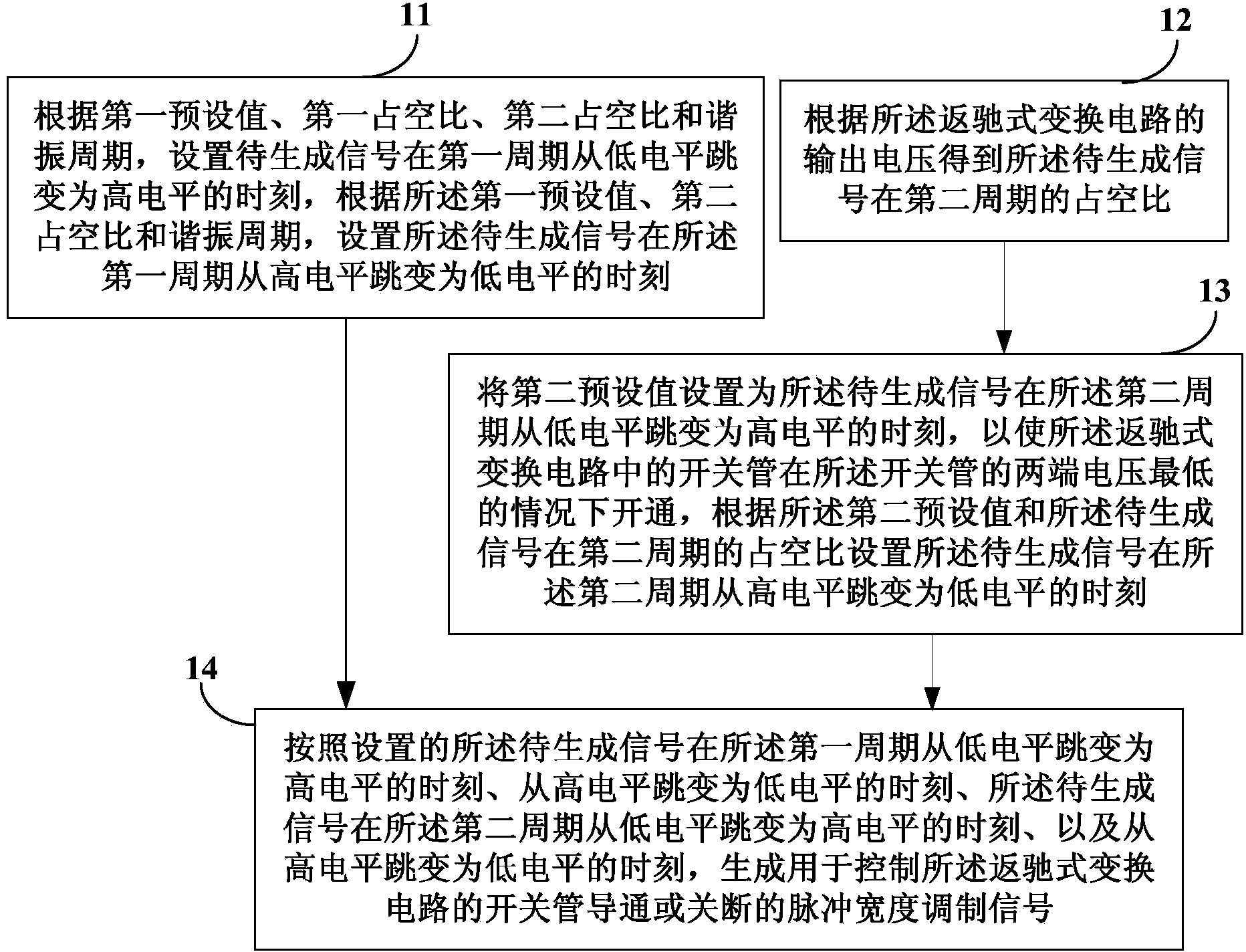
[0028] figure 1 It is a flowchart of a method for generating a pulse width modulation signal provided by an embodiment of the present invention. Such as figure 1 As shown, the method for generating a pulse width modulation signal includes: Step 11 to Step 15.

[0029] In step 11, according to the first preset value, the first duty cycle, the second duty cycle and the resonance cycle, set the moment ...


PUM


Abstract

The invention discloses a power supply and a pulse width modulation generating method and device. According to the method, by means of setting the moment of a generated signal turning into high level from low level in a first period, the moment of the generated signal turning into the low level from the high level in the first period, the moment of a signal, turning into high level from low level in a second period, to be generated and the moment of the signal, turning into the low level from the high level in the second period, to be generated, the generated PMW signal in the two periods of a switch tube is made to achieve the purpose that the switch tube is powered on at least one time when the voltage passing through the two ends of the switch tube is the minimum, power-on losses of switch tubes in a flyback type conversion circuit are reduced, and the power-on efficiency of the switch tube is improved.

Description

technical field [0001] The invention relates to power supply technology, in particular to a power supply, a method and a device for generating a pulse width modulation signal. Background technique [0002] In the switching power supply, the flyback (FLYBACK) conversion circuit working in the DCM (Discontinuous Current Mode, that is, the inductor current discontinuous mode) mode, its output terminal obtains energy when the primary winding of the transformer is disconnected from the power supply. The on-off between the primary winding of the transformer and the power supply is controlled by turning on or off the switch tube. The turn-on or turn-off of the switch tube is controlled by the drive signal PWM. [0003] When the driving signal is at a low level, the switching tube is turned off, and the transformer transfers energy to the load; when the driving signal is at a high level, the switching tube is turned on, and the primary winding of the transformer stores energy. [...

Claims


Application Information

Patent Timeline
Patent Type & Authority Applications(China)
IPC IPC(8): H02M1/08
Inventor 翦志强张灿烂戴路加
Owner SHENZHEN GOLDEN HIGHWAY TECH CO LTD
Why Eureka
Try Eureka