Flyback conversion circuit, on-off control circuit adaptive to flyback conversion circuit and valley bottom detection circuit and method

A flyback conversion and detection circuit technology, applied in the field of electronics, can solve the problems of large circuit turn-on loss, large error, large resonance cycle change, etc.

Active Publication Date: 2015-06-10
SILERGY SEMICON TECH (HANGZHOU) CO LTD
View PDF6 Cites 3 Cited by
  • Summary
  • Abstract
  • Description
  • Claims
  • Application Information

AI Technical Summary

Problems solved by technology

However, when the operating frequency of the circuit is high, the resonance period changes greatly, and there is a large error between the bottom time detected by the above technology and the actual bottom time, and the use of this technical solution leads to a large turn-on loss of the circuit

Method used


Image

  • Flyback conversion circuit, on-off control circuit adaptive to flyback conversion circuit and valley bottom detection circuit and method
  • Flyback conversion circuit, on-off control circuit adaptive to flyback conversion circuit and valley bottom detection circuit and method
  • Flyback conversion circuit, on-off control circuit adaptive to flyback conversion circuit and valley bottom detection circuit and method

Examples


Embodiment 1

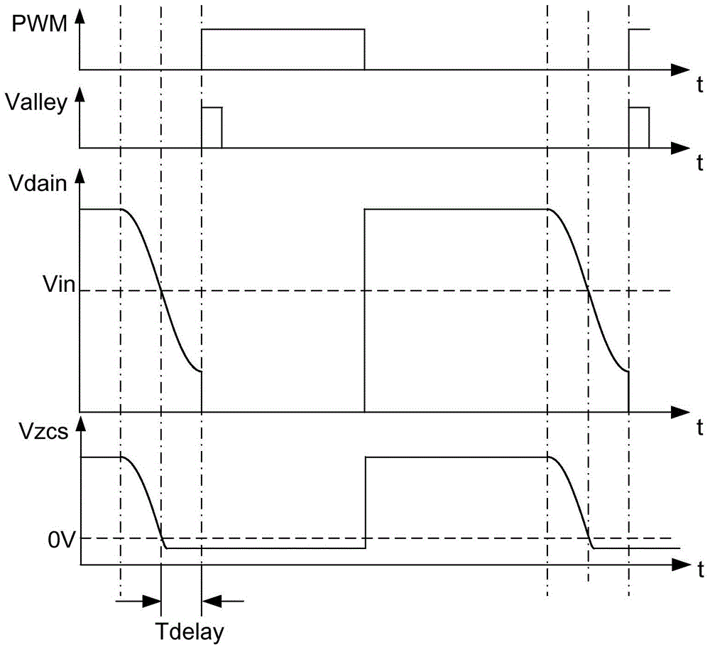
[0063] see Figure 4 As shown, this embodiment provides a switching voltage valley detection method suitable for a flyback conversion circuit, and the method mainly includes the following steps:

[0064] Step 401: When the switching voltage Vdrain resonantly drops to be equal to the DC input voltage Vin of the flyback conversion circuit, proceed to step 402; otherwise, return to this step.

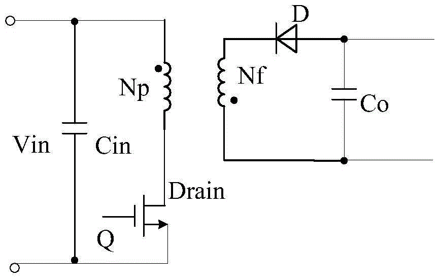
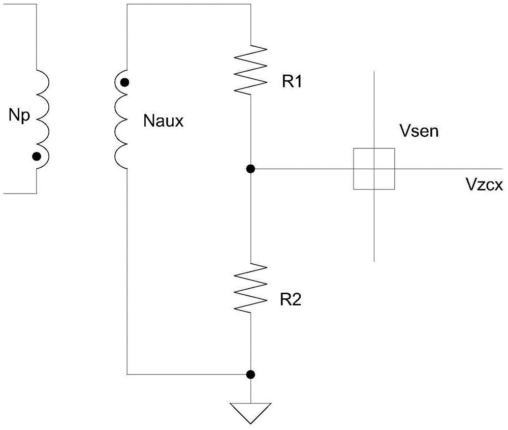
[0065] As a demonstration of this embodiment, you can, but not limited to, refer to figure 2 The shown circuit sets the auxiliary winding Naux, and uses the sampled voltage obtained through the auxiliary winding Naux as the detection voltage Vzcs. In this way, it can be determined whether the switching voltage Vdrain resonantly drops to the DC input voltage Vin of the flyback conversion circuit by detecting whether the detection voltage Vzcs crosses zero. , but it is actually not limited to this, and other technical solutions can also be used to realize this step.

[0066] figure 2 Fo...

Embodiment 2

[0083] This embodiment provides a switching voltage valley detection circuit 800 suitable for a flyback conversion circuit, see Figure 8 As shown, the bottom detection circuit 800 mainly includes a switch voltage detection circuit 801 and a bottom detection signal generation circuit 802 . It works as follows:

[0084]The output end of the switching voltage detection circuit 801 is connected to the input end of the valley detection signal generation circuit 802, and is used to detect the switching voltage Vdrain of the flyback conversion circuit. When the switching voltage Vdrain resonantly drops to be equal to the DC input voltage Vin of the flyback conversion circuit , output the control signal to the bottom detection signal generation circuit 802; after the bottom detection signal generation circuit 802 receives the control signal (that is, after the switch voltage Vdrain resonates and drops to be equal to the DC input voltage Vin), the delay is equal to 1 / of the resonance...

Embodiment 3

[0100] see Figure 9 As shown, this embodiment provides a switch control circuit 900 suitable for the switching voltage of a flyback conversion circuit. The switch control circuit 900 includes the valley detection circuit 800 and the switch control module 901 shown in Embodiment 2.

[0101] Wherein, the output end of the valley detection circuit 800 is connected to an input end of the switch control module 901 for inputting the valley detection signal Valley to it. After the switch control module 901 receives the valley detection signal Valley, it Output an effective switch control signal (generally a PMW signal) to turn on the power switch tube Q of the flyback conversion circuit at the time when the current switch voltage Vdrain resonates to the valley, so as to realize the valley conduction of the power switch tube Q and reduce the switching circuit. Turn-on loss.

[0102] The switch control circuit 900 of this embodiment can be applied to any flyback conversion circuit. ...


PUM


Abstract

The invention provides a flyback conversion circuit, an on-off control circuit adaptive to the flyback conversion circuit and a valley bottom detection circuit and method. The valley bottom detection method comprises the step that when switching voltage resonance of the flyback conversion circuit is lowered to be equal to direct current input voltage of the flyback conversion circuit, a first time period is delayed, valley bottom detection signals are output and mark the current switching voltage resonance to the wave trough, and the duration of the first time period is one fourth of the resonant period of a primary winding and a primary equivalent resonant capacitance. By means of the technical scheme, the valley bottom detection precision of switching voltage can be improved.

Description

technical field [0001] The invention relates to the field of electronics, in particular to a flyback conversion circuit, a switch control circuit applicable to the circuit, a valley detection circuit and a method. Background technique [0002] see figure 1 As shown, the flyback conversion circuit is a DC switching transformer composed of the primary winding Np and the secondary winding Nf inserted between the power switch tube and the freewheeling diode of the Buck-Boost conversion circuit to achieve electrical isolation between the input and output. -DC conversion circuit, the flyback conversion circuit transmits energy to the load when the power switch tube is turned off. [0003] During the working process of the flyback conversion circuit, the primary winding Np is used as the excitation inductance, and the equivalent resonant capacitance of the primary side (including the junction capacitance of the switch tube, the refraction capacitance of the secondary side of the t...

Claims


Application Information

Patent Timeline
Patent Type & Authority Applications(China)
IPC IPC(8): H02M3/335G01R19/175
CPCG01R19/175H02M3/335H02M1/0009H02M1/0048Y02B70/10
Inventor 李新磊李乐白永江胡志亮
Owner SILERGY SEMICON TECH (HANGZHOU) CO LTD
Why Eureka
Try Eureka