Neutral-point active clamping three-level inverter, control method and control device
A three-level inverter, clamping technology, applied in the output power conversion device, electrical components, high-efficiency power electronic conversion and other directions, can solve the problems of poor stability, uneven heating of switching tubes, low power conversion efficiency, etc. Achieve the effect of reducing voltage stress, improving power conversion efficiency, and uniform heating
- Summary
- Abstract
- Description
- Claims
- Application Information
AI Technical Summary
Problems solved by technology
Method used
Image
Examples
Embodiment 1
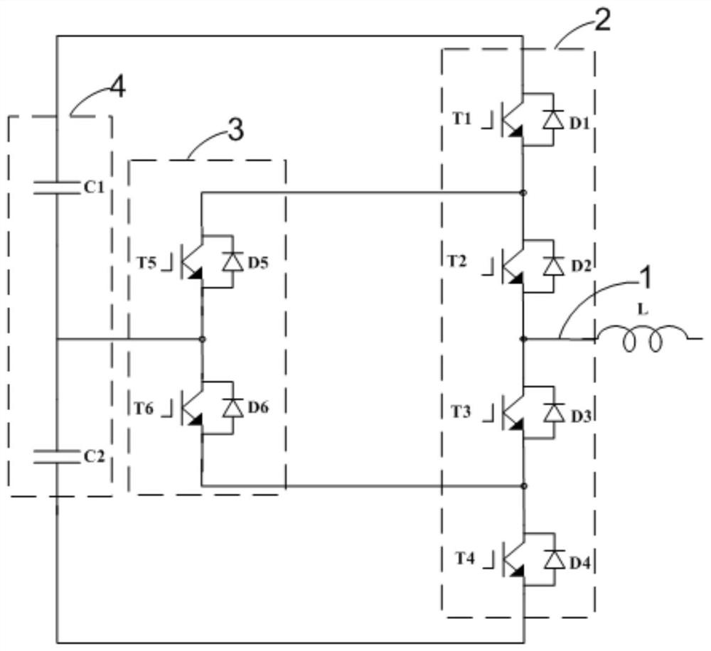
[0035] like figure 1 as shown, figure 1 It is a circuit diagram of a midpoint active clamping three-level inverter provided by an embodiment of the present invention. The midpoint active clamping three-level inverter includes: a bridge arm unit 2, and the bridge arm unit 2 connected to the clamping unit 3, and the bridge arm output terminal 1 connected to the bridge arm unit 2.
[0036] The bridge arm unit 2 includes a first switch tube T1, a second switch tube T2, a third switch tube T3, and a fourth switch tube T4 connected in series in sequence, corresponding to the first switch tube T1 and the second switch tube T4 one by one. The first diode D1 , the second diode D2 , the third diode D3 and the fourth diode D4 are connected in antiparallel to the T2 , the third switch tube T3 , and the fourth switch tube T4 .
[0037] The clamping unit 3 includes a fifth switch tube T5 and a sixth switch tube T6 connected in series in sequence, corresponding to the fifth diode D5 and th...
Embodiment 2
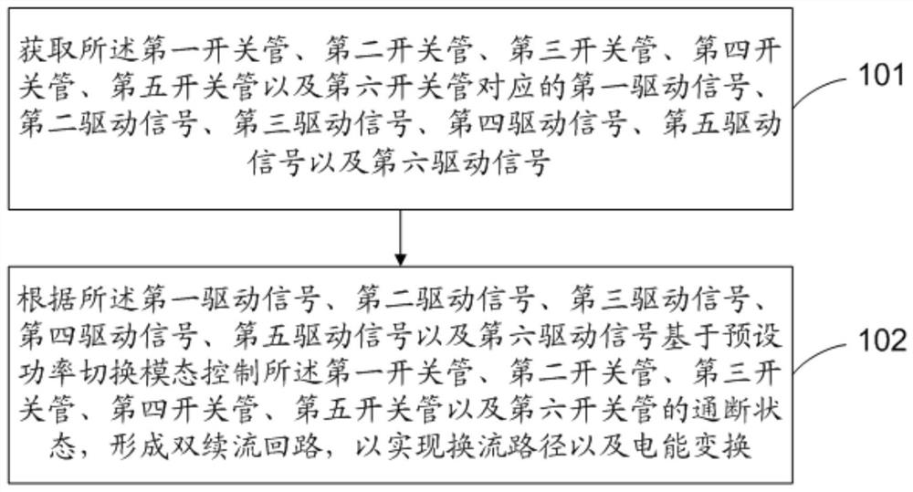
[0056] like figure 2 as shown, figure 2 It is a flow chart of a control method for a midpoint active clamping three-level inverter provided in an embodiment of the present invention, which is used for the midpoint active clamping three-level inverter provided in the above embodiment, The control method of the midpoint active-clamped three-level inverter includes the following steps:
[0057] Step 101. Obtain the first drive signal, the second drive signal, and the third drive signal corresponding to the first switch tube, the second switch tube, the third switch tube, the fourth switch tube, the fifth switch tube, and the sixth switch tube. signal, the fourth driving signal, the fifth driving signal and the sixth driving signal.
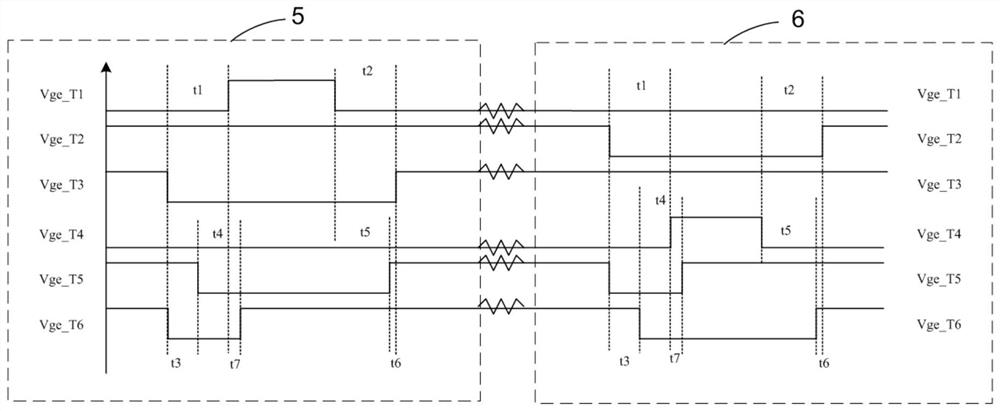
[0058] Wherein, the first driving signal, the second driving signal, the third driving signal, the fourth driving signal, the fifth driving signal and the sixth driving signal are used to drive the first switching tube, the second switching tube,...
Embodiment 3
[0094] like Figure 13 as shown, Figure 13 It is a schematic structural diagram of a control device for a midpoint active-clamped three-level inverter provided by an embodiment of the present invention. The control device 400 for a midpoint active-clamped three-level inverter includes:
[0095] The obtaining unit 401 is configured to obtain the first drive signal, the second drive signal, the second drive signal, The third driving signal, the fourth driving signal, the fifth driving signal and the sixth driving signal.
[0096] Wherein, the first driving signal, the second driving signal, the third driving signal, the fourth driving signal, the fifth driving signal and the sixth driving signal are used to drive the first switching tube, the second switching tube, and the third switching tube , the fourth switching tube, the fifth switching tube and the sixth switching tube. The first driving signal, the second driving signal, the third driving signal, the fourth driving si...
PUM
 Abstract
Description
Claims
Application Information
 - R&D
- Intellectual Property
- Life Sciences
- Materials
- Tech Scout
- Unparalleled Data Quality
- Higher Quality Content
- 60% Fewer Hallucinations
Browse by: Latest US Patents, China's latest patents, Technical Efficacy Thesaurus, Application Domain, Technology Topic, Popular Technical Reports.
© 2025 PatSnap. All rights reserved.Legal|Privacy policy|Modern Slavery Act Transparency Statement|Sitemap|About US| Contact US: help@patsnap.com


