Driving circuit for driving power switch device

A technology for power switching devices and driving circuits, applied in circuits, electronic switches, semiconductor devices, etc., can solve the problems of speeding up the switching speed, slow switching speed, and high turn-on power consumption, etc. Effect

Active Publication Date: 2018-07-24
武汉英弗耐斯电子科技有限公司
View PDF11 Cites 3 Cited by
  • Summary
  • Abstract
  • Description
  • Claims
  • Application Information

AI Technical Summary

Problems solved by technology

[0004] In view of the above defects or improvement needs of the prior art, the present invention provides a driving circuit for driving power switching devices, the purpose of which is to precisely control the gate drive current of the power switching devices in stages through the circuit, and maintain the power switching device. Accelerate the switching speed and reduce the turn-on loss when the current peak of the device turn-on process remains unchanged, solving the problem that the open-loop control circuit adopted in the prior art only relies on adjusting the gate resistance to achieve a compromise between the current peak and turn-on loss, resulting in turn-on power consumption The problem of large and slow switching speed

Method used


Image

  • Driving circuit for driving power switch device
  • Driving circuit for driving power switch device
  • Driving circuit for driving power switch device

Examples


Embodiment Construction

[0026] In order to make the object, technical solution and advantages of the present invention clearer, the present invention will be further described in detail below in conjunction with the accompanying drawings and embodiments. It should be understood that the specific embodiments described here are only used to explain the present invention, not to limit the present invention. In addition, the technical features involved in the various embodiments of the present invention described below can be combined with each other as long as they do not constitute a conflict with each other.

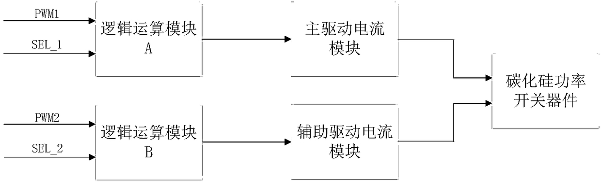
[0027] The driving circuit for driving the power switching device provided by the present invention precisely controls the driving current of the power switching device in stages through the design of the circuit, so as to accelerate the switching speed and reduce the turn-on loss while maintaining the current peak value unchanged ; In order to solve the problem that the open-loop control circui...


PUM


Abstract

The invention discloses a driving circuit for driving a power switch device. The driving circuit comprises a first logic operation module, a second logic operation module, a main driving current module and an auxiliary driving current module; the first and second input ends of the first logic operation module are used for accessing a first control signal and a first bit selection signal; the inputend of the main driving current module is connected with the output end of the first logic operation module; the output end is used for connecting a grid electrode of the power switch device; the first and second input ends of the second logic operation module are used for accessing a second control signal and a second bit selection signal; the input end of the auxiliary driving current module isconnected with the output end of the second logic operation module, and the output end is used for connecting the grid electrode of the power switch device; the output current of the main driving current module and the auxiliary driving module commonly constructs the gate driving current of the power switch device, the precise and staged control on the gate driving current can be realized throughthe control on the output current of the main driving current module and the auxiliary driving module, and the device on-off speed is accelerated and the open loss is reduced under the condition of maintaining the current peak unchanged.

Description

technical field [0001] The invention belongs to the technical field of integrated circuit design, and in particular relates to a driving circuit for driving a power switching device. Background technique [0002] Power switching devices such as silicon carbide power switching devices and IGBTs have broad development prospects and will be widely used due to their excellent physical, chemical and electrical characteristics, such as high voltage resistance, high temperature resistance, and high frequency, which are far superior to traditional silicon-based power switching devices. Used in various power electronic equipment. [0003] Since silicon carbide power switching devices, IGBT and other high-power devices will generate large power consumption during the switching process, reducing the switching loss through the improvement of the drive circuit can not only prevent the device from being damaged due to severe heat, but also save energy. The open-loop control of the tradit...

Claims


Application Information

Patent Timeline
Patent Type & Authority Applications(China)
IPC IPC(8): H03K17/04H03K17/041H03K17/567H03K17/687
CPCH03K17/0406H03K17/04106H03K17/567H03K17/687H03K2217/0036H03K2217/0081
Inventor 童乔凌
Owner 武汉英弗耐斯电子科技有限公司
Why Eureka
Try Eureka