Eureka AIR delivers breakthrough ideas for toughest innovation challenges, trusted by R&D personnel around the world.

Nail extractors

A technology of nails and nails, which is applied in the field of nail extractors, can solve the problems of failure to pull out, difficult to remove the nails, unable to fix the nails completely, etc., and achieves the effect of convenient operation and use

Inactive Publication Date: 2008-10-15
APEX MFG
View PDF0 Cites 3 Cited by
  • Summary
  • Abstract
  • Description
  • Claims
  • Application Information

AI Technical Summary

Problems solved by technology

[0007] In summary, the problem with the known structure of the nail puller is that it cannot completely fix the pulled out nails, and it is easy to pop or fly the nails to other places at the moment of pulling out the nails. It is easy to cause difficulty or failure to remove the needle during use

Method used


Image

  • Nail extractors
  • Nail extractors
  • Nail extractors

Examples


Embodiment 1

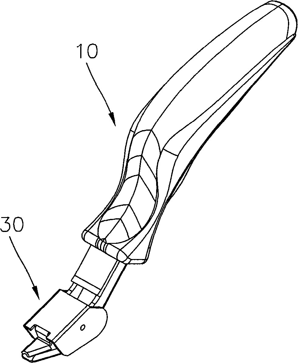
[0047] refer to image 3 Referring to Fig. 5, the present invention includes a handle 10, a nail puller 20 and a nail presser 30; wherein:

[0048] The handle 10 has a first end and a second end. The first end forms a grip portion 11 for the user to hold, and the second end of the handle 10 defines a coupling groove 12 . The handle 10 has a blocking piece 13 extending from the upper side of the open end of the coupling groove 12 .

[0049] The nail pulling member 20 is fixed at one end of the handle 10 to achieve the effect of pulling out the nail needle 90 . The nail pulling member 20 has a U-shaped structure, and has shaft holes 21 on two side walls 201 thereof for passing a pivot shaft 22 . The front part of the nail pulling part 20 is provided with a nail pulling part 23, which is used to pull out the nail pins 90 that are nailed on the paper 91 (or wood). Tilted structure.

[0050] The rear section of the nail pulling member 20 forms a joint portion 24 for inserting a...

Embodiment 2

[0063] refer to Figure 12 , is the second embodiment of the present invention. This embodiment is substantially the same as the above-mentioned embodiments, the difference lies in that a nail-pulling hole 231 is defined in the nail-pulling portion 23 . The nail-pulling hole 231 is used for the user to pull out the nails that still have one-side stitches left in the paper.


PUM


Abstract

The invention provides a staple remover, which comprises a handle, a staple removing component and a staple pressing component; the handle is provided with a first end and a second end, wherein the first end forms a handling part, and the second end is provided with a linking groove; the staple removing component is provided with a pivot, a staple removing part is arranged in the front part of the staple removing component, and a linking part is formed in the rear part of the staple removing component and is fixedly inserted in the linking groove of the handle; the staple pressing component is pivoted on the pivot of the staple removing component, a staple pressing sheet extending from the front of the upper wall of the staple pressing component is formed, and the staple pressing part extending downwards is formed on the two sides of the staple pressing sheet, and the centre of gravity of the staple pressing component is positioned in the front of the pivot, a butting part and a supporting part protruding the bottom wall of the staple removing component are formed on the bottom edge of the staple pressing component and are used for butting with the paper. The staple pressing sheet is used for pressing the staple by the contact with the staple removing part through the dead weight of the staple removing part.

Description

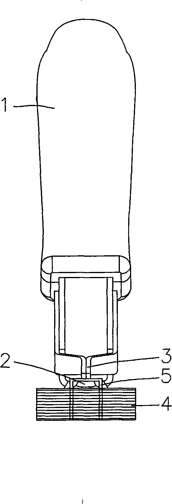
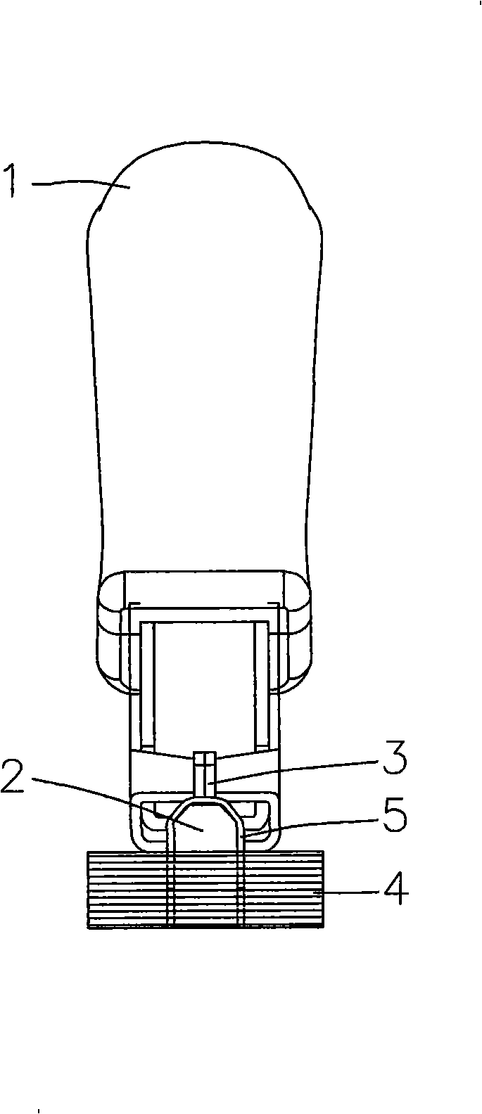
technical field [0001] The invention relates to a nail needle puller. Background technique [0002] Please refer to figure 1 and figure 2 , is a structure of a known nail puller 1, the nail puller 1 has a nail puller 2 and a nail pressing member 3 pivotally arranged on the nail puller 1. The nail puller 1 is used to pull out the nails 5 bound on the paper 4 (or wood). During use, the nail puller 2 is inserted between the nails 5 and the paper 4, and the nail pressing part 3 is pressed on the nails. 5, and then the nail 5 is tilted to achieve the effect of pulling out the nail 5. [0003] This known structure still has many shortcomings in actual use. Therefore, during the process of pulling out the nail needle 5 of the nail puller 1, the nail pressing part 3 is pressed on the middle section of the nail needle 5, so in the process of tilting, The middle section place of nail needle 5 can be out of shape usually as figure 2 The convex shape shown in the figure has the d...

Claims


Application Information

Patent Timeline
IPC IPC(8): B25C11/00
Inventor 蔡富丞
Owner APEX MFG
Why Eureka
Eureka Blog
Learn More