

Brake pressure cylinder device and brake tongs device
A brake pressure and cylinder device technology, which is applied in the field of brake pressure cylinder devices and brake caliper devices, can solve the problems of complicated and bulky mechanisms, difficulty in realizing the adjustable range and non-adjustable range of push rods, etc., to prevent Organizational complexity and the effect of suppressing complexity
Inactive Publication Date: 2008-10-15
NABLESCO CORP
View PDF3 Cites 12 Cited by
- Summary
- Abstract
- Description
- Claims
- Application Information
AI Technical Summary
Problems solved by technology
However, in Patent Document 1, as the above-mentioned protruding length adjustment mechanism, only a form having a friction ring assembly is disclosed, and as a mechanism for limiting the relative movement amount of the output piston having a push rod and the friction ring assembly, only a form is disclosed. A mechanism with a special structure such as a stepped shaft corresponding to the protrusion length adjustment mechanism realized by the friction ring assembly
Therefore, in a brake pressure cylinder device having a common brake mechanism and a spring brake mechanism, if the protrusion length adjustment mechanism of the structure described in Patent Document 1 is incorporated, the mechanism will become complicated and bulky.
In addition, in the brake pressure cylinder device with a common brake mechanism and a spring brake mechanism, using the special structure disclosed in Patent Document 1, it is difficult to realize the adjustable range and non-adjustable range of the protrusion length of the limit push rod in the protrusion length adjustment mechanism. range of institutions
Method used
View moreImage
Smart ImageViewing Examples

Examples
Embodiment Construction
Login to View More PUM
 Abstract
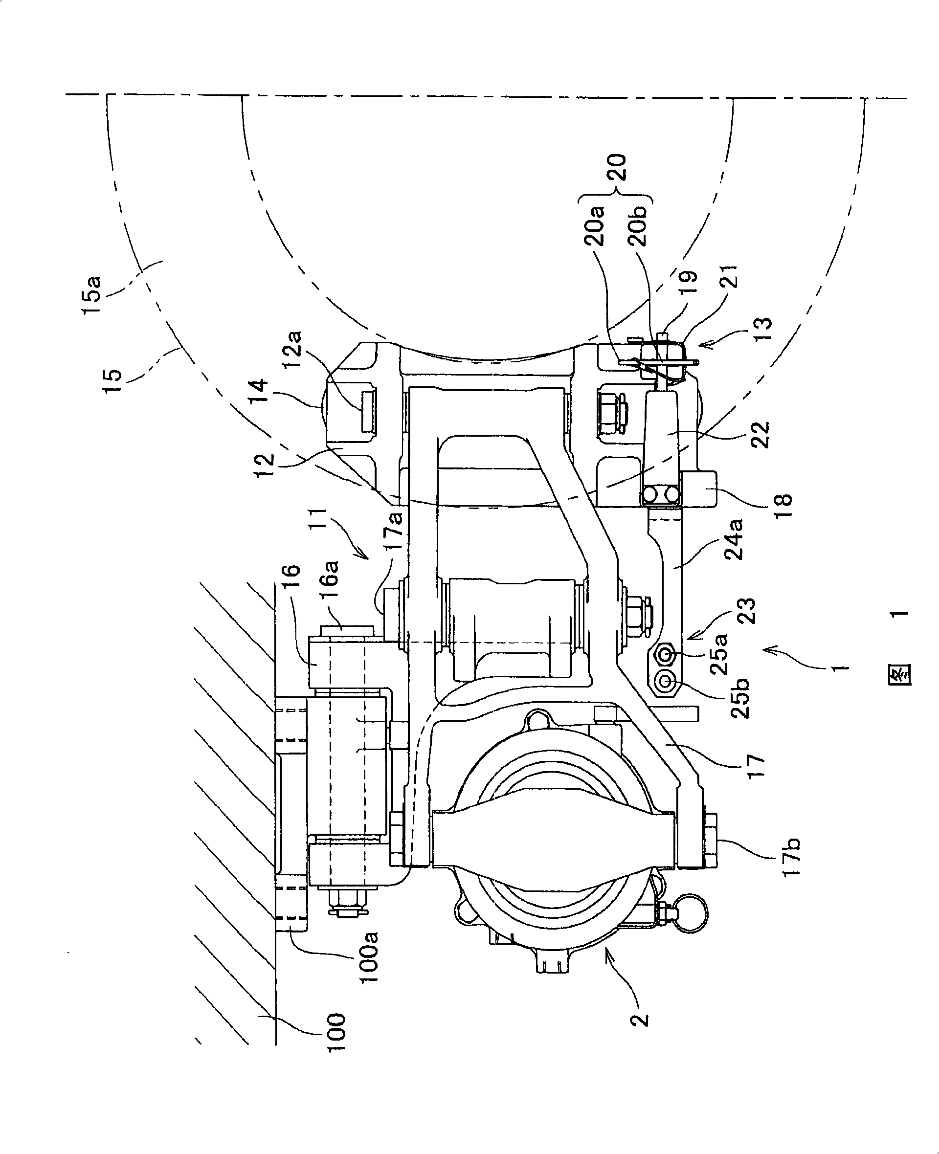
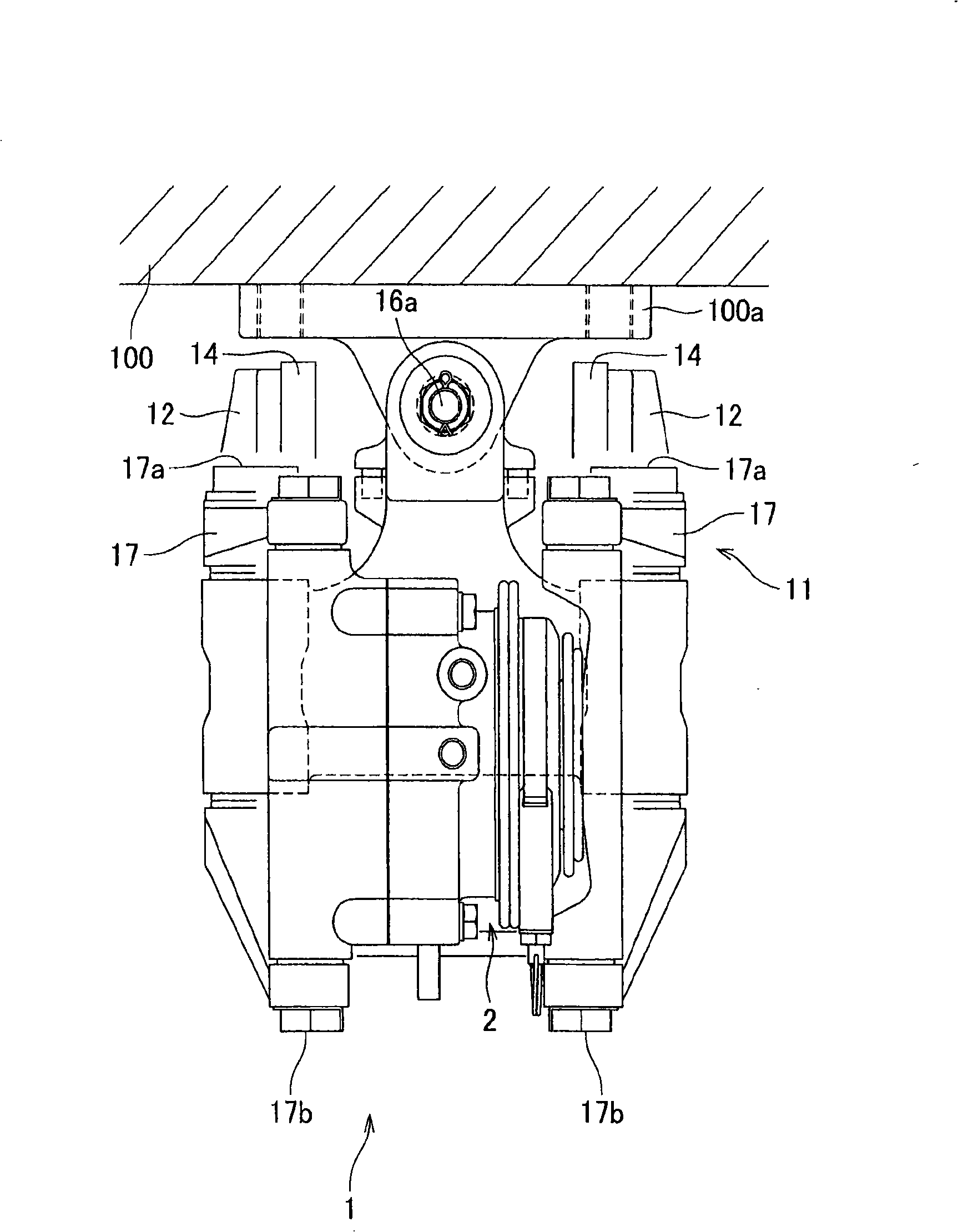
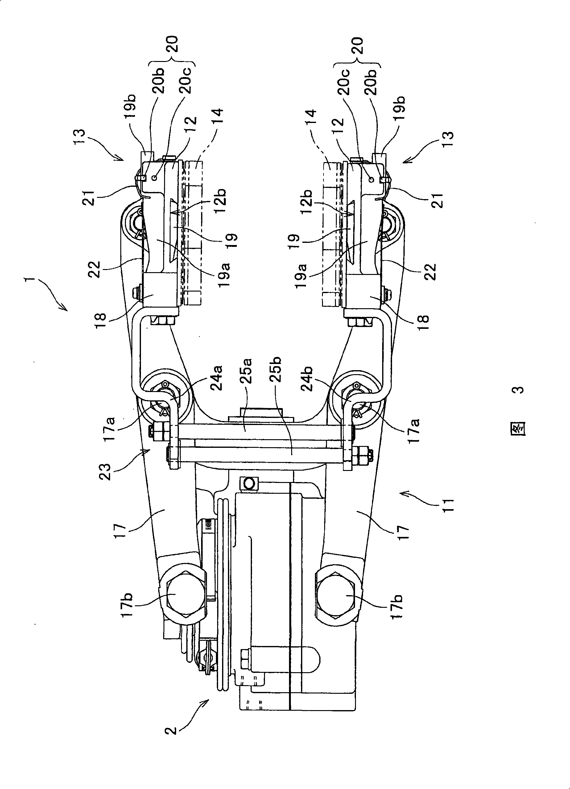
The invention relates to a brake pressure cylinder device and a brake caliper device; the brake pressure cylinder device has a common brake mechanism, a spring brake mechanism, a push rod and a projection length adjusting mechanism; the projection length adjusting mechanism has a leading part which is mounted on the push rod by moving together with the push rod and acting on the established resistance when the push rod moves for adjusting the projection length projected from the cylinder body. The projection length adjusting mechanism further has a recess arranged in the leading part, and a limiting mechanism; the limiting mechanism has a blocking part blocked with the recess arranged between a second piston and a first spring for limiting the movable area of the first piston on the movable direction.
Description
Brake pressure cylinder device and brake caliper device This application claims priority based on Japanese Patent Application No. 2007-104970 (filed on April 12, 2007). technical field The present invention relates to a brake pressure cylinder device and a brake caliper device having the brake pressure cylinder device. Adjust the protruding length of the pushrod from the cylinder body. Background technique Regarding the brake pressure cylinder device that can automatically adjust the protruding length of the push rod from the cylinder body, Patent Document 1 (Japanese Patent Publication No. 6-67725 (claim 1, FIG. 2)) discloses a brake cylinder having the following structure: A brake pressure cylinder device, the brake pressure cylinder device has in the cylinder: an output piston, a push rod connected with a brake shoe for braking the wheel tread; a friction ring assembly, which is composed of two circular plates clamped An elastic ring is used to expand it radially out...
Claims
Login to View More Application Information
Patent Timeline
 IPC IPC(8): F16D65/32F16D65/18F16D65/28
CPCF16D65/56F16D2125/04F16D2125/08F16D2125/10
Inventor麻野吉雄
OwnerNABLESCO CORP