Binocular near-eye display system
A near-eye display and binocular technology, applied in optics, instruments, optical components, etc., can solve problems such as affecting eyesight, eye fatigue, and difference in imaging effects, and achieve the effect of simplifying the structure and reducing costs
- Summary
- Abstract
- Description
- Claims
- Application Information
AI Technical Summary
Problems solved by technology
Method used
Image
Examples
Embodiment 1
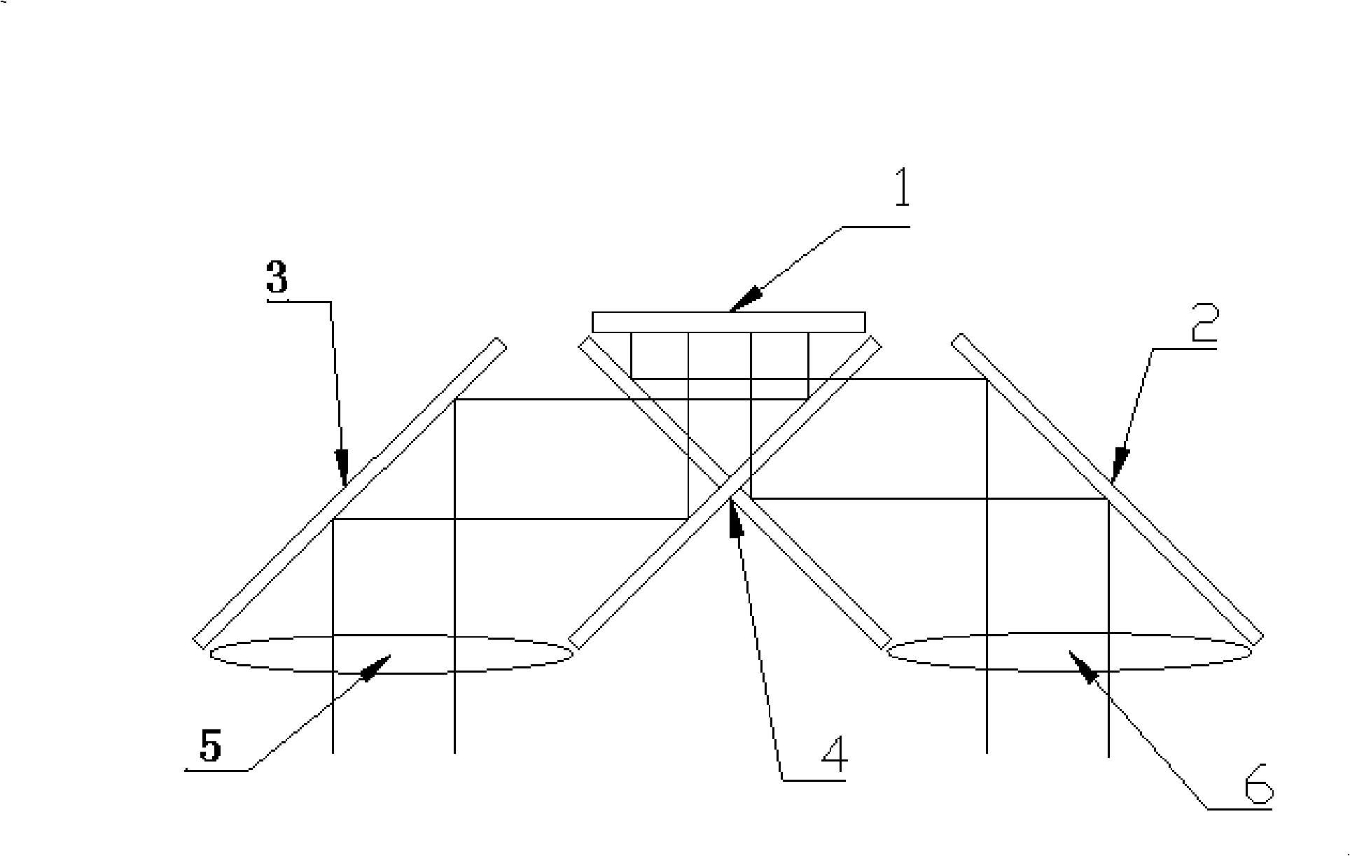
[0027] Such as figure 1 As shown, the binocular near-eye display system in this example includes a microdisplay device 1 , a reflector 2 , a reflector 3 , an X-shaped polarization beam splitting reflective plane mirror 4 , a left-eye eyepiece 5 and a right-eye eyepiece 6 . Reflector 3 and left-eye eyepiece 5 constitute a left-eye eyepiece system, and reflector 2 and right-eye eyepiece 6 constitute a right-eye eyepiece system.
[0028] Its working principle is: the light emitted by the micro-display device 1 is split by the X-shaped polarized spectroscopic reflective plane mirror 4, and then reflected by the mirror 2 and the mirror 3 to the left eyepiece 5 and the right eyepiece 6, and then enters the left eye respectively. and right eye.
[0029] The microdisplay device in this example adopts a non-polarized light microdisplay device, and the light emitted is natural light. The light splitting system adopts an X-shaped polarized beam splitting reflector, and what the reflecto...
Embodiment 2
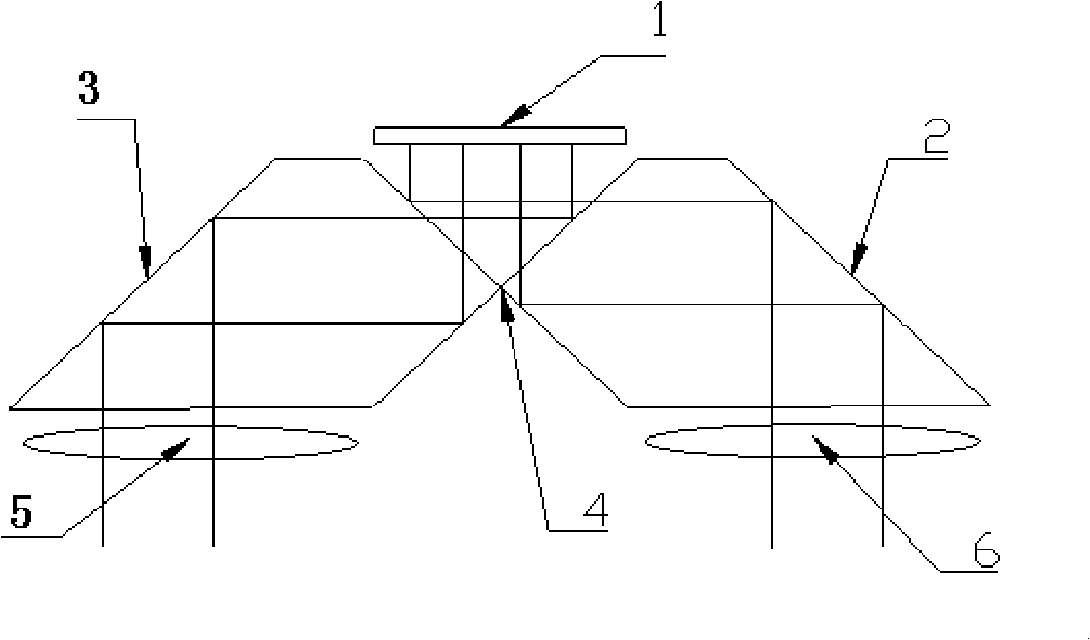
[0031] Such as figure 2 As shown, the binocular near-eye display system in this example includes a microdisplay device 1 , a polarization splitting reflective prism 2 , a polarization splitting reflective prism 3 , a left-eye eyepiece 5 and a right-eye eyepiece 6 . Here, the polarization beam-splitting reflective prism 2 and the polarization beam-splitting reflector 3 are combined into an X-shaped polarization beam-splitting reflector 4 to form a beam-splitting system. 2 and the right-eye eyepiece 6 constitute the right-eye eyepiece system.
[0032] Its working principle is: the light emitted by the micro-display device 1 passes through the polarization beam-splitting reflective prisms 2 and 3, and then reflects to the left-eye eyepiece 5 and right-eye eyepiece 6, and then enters the left eye and the right eye respectively.
[0033] The micro-display device in this example uses a non-polarized light micro-display device, the light emitted is natural light, and the light-spli...
Embodiment 3
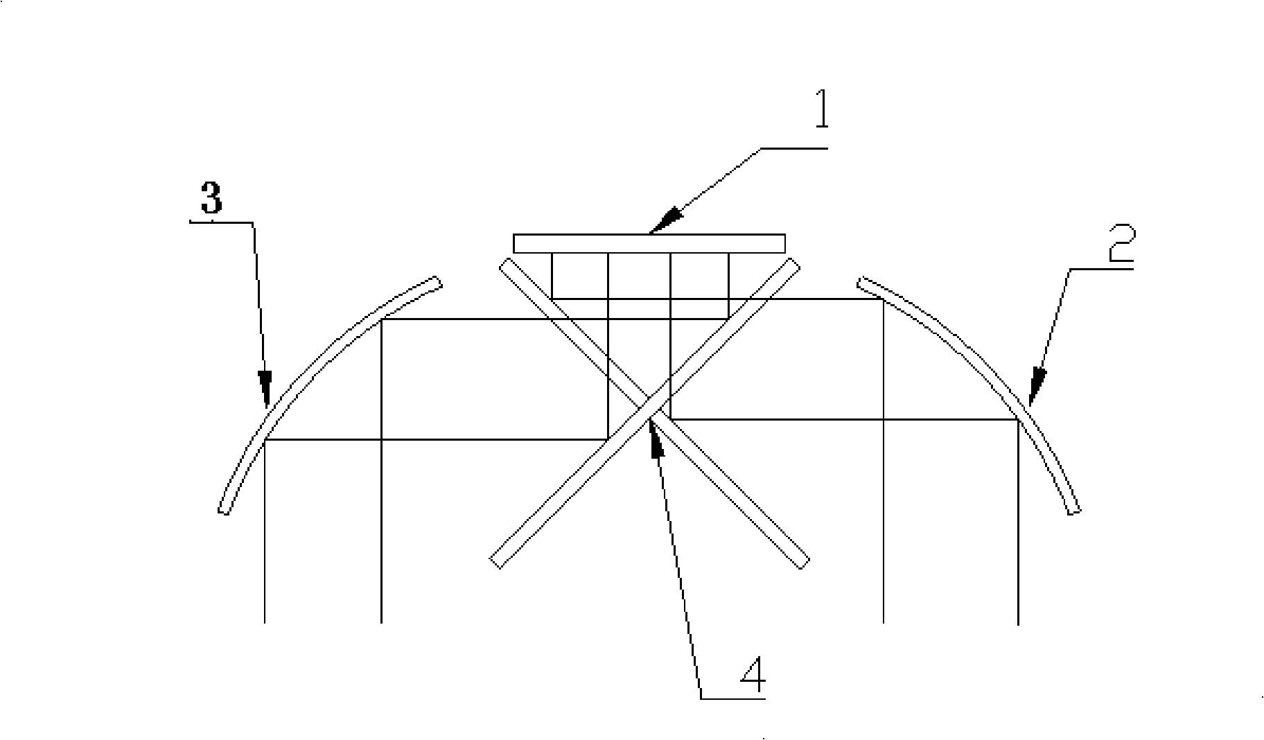
[0035] Such as image 3 As shown, the binocular near-eye display system in this example includes a microdisplay device 1 , a curved reflector 2 , a curved reflector 3 , and an X-shaped polarization beam splitting reflective plane mirror 4 .
[0036] Its working principle is: the light emitted by the micro-display device 1 is split by the X-shaped polarized beam-splitting mirror 4, then reflected by the curved mirror 2 and the curved mirror 3, and then enters the entrance pupils of the left eye and the right eye. Here the curved mirrors 2 and 3 function as eyepieces, forming a left-eye eyepiece system and a right-eye eyepiece system.
[0037] The microdisplay device in this example adopts a non-polarized light microdisplay device, the light emitted is natural light, and the light splitting system adopts an X-shaped polarized light splitting reflective plane mirror.
PUM
 Abstract
Description
Claims
Application Information
 - R&D
- Intellectual Property
- Life Sciences
- Materials
- Tech Scout
- Unparalleled Data Quality
- Higher Quality Content
- 60% Fewer Hallucinations
Browse by: Latest US Patents, China's latest patents, Technical Efficacy Thesaurus, Application Domain, Technology Topic, Popular Technical Reports.
© 2025 PatSnap. All rights reserved.Legal|Privacy policy|Modern Slavery Act Transparency Statement|Sitemap|About US| Contact US: help@patsnap.com


