Electromagnetic stove time-limiting automatic switch on and off protection device

A protection device, the technology of electromagnetic cooker, applied in the direction of signal device, visible signal device, household stove/stove, etc., can solve the problem of not being able to power off automatically, and achieve the effect of avoiding manual power off and reducing the possibility of fire

Inactive Publication Date: 2008-10-15
HARBIN INST OF TECH
View PDF0 Cites 3 Cited by
  • Summary
  • Abstract
  • Description
  • Claims
  • Application Information

AI Technical Summary

Problems solved by technology

[0003] In order to solve the problem that the electromagnetic cooker currently used on the railway dining car cannot automatically cut off the power, the present invention provides a time-limited automatic power on and off protection device for the electromagnetic cooker

Method used


Image

  • Electromagnetic stove time-limiting automatic switch on and off protection device

Examples


specific Embodiment approach 1

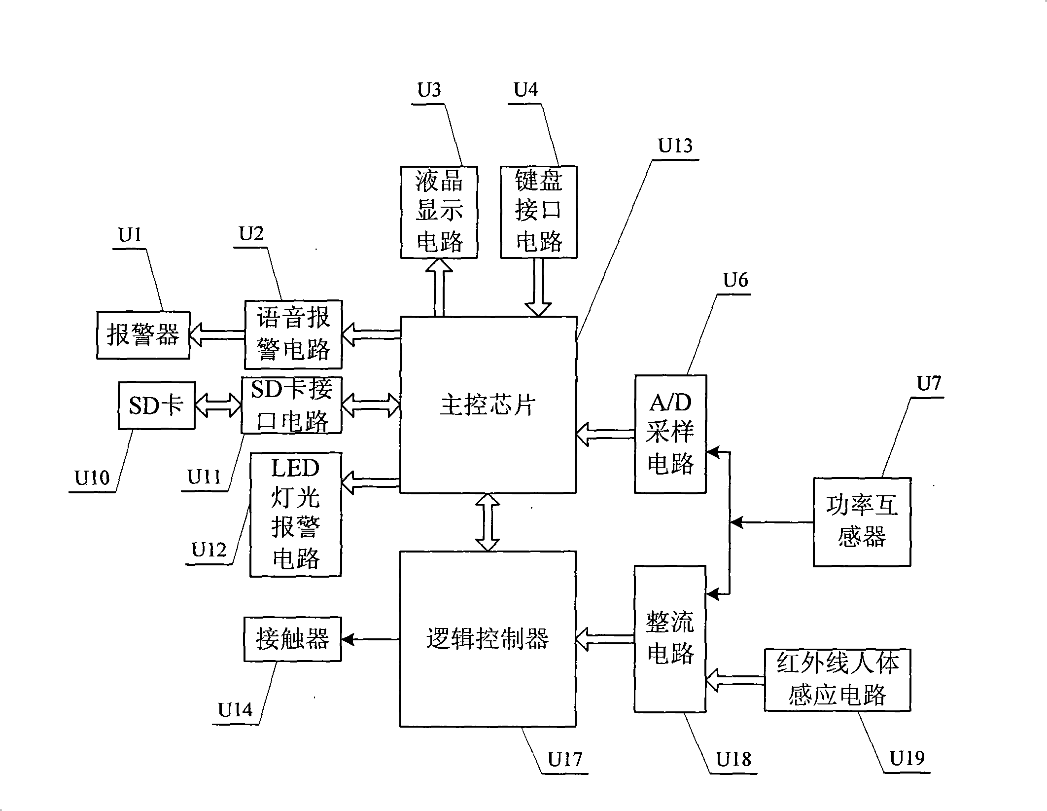
[0014] Specific implementation mode one: see figure 1 , this embodiment consists of the following units:

[0015] The power sensor U7, when monitoring the working signal of the electromagnetic cooker, sends the start-up signal of the electromagnetic cooker to the PLC programmable logic controller U17 through the rectifier circuit U18, and at the same time sends the output signal of the power sensor U7 through the A / D sampling circuit U6 Convert it into A / D sampling signal and send it to the main control chip U13;

[0016] PLC programmable logic controller U17, when receiving the start power signal of the electromagnetic cooker from the power sensor U7, starts the internal timer to time the working time of the electromagnetic cooker, and after the working time ends, sends a control signal to disconnect the contactor U14, and At the same time, start the internal timer to set the power-off time. After the power-off time is over, send the control signal to make the contactor U14 ...

specific Embodiment approach 2

[0024] Specific implementation mode two: see figure 1 , this embodiment adds the following units on the basis of the specific embodiment one:

[0025] The SD card interface circuit U11 stores the automatic power-off time of each induction cooker, the unmanned time of the dining car and the consumed electric energy value in the SD card U10, and calls the information in the SD card U10 according to the requirements of the main control chip U13.

[0026] SD card U10 and SD card interface circuit U11 form an SD card storage system. The stored data includes three parts: the cumulative value of electric energy, the unmanned time of the dining car and the automatic power-off time, which can be used by operators and maintenance personnel to understand the operation of the entire system and increase system security and operational efficiency.

specific Embodiment approach 3

[0027] Specific implementation mode three: see figure 1 , this embodiment adds the following units on the basis of the specific embodiment one:

[0028] The LED light alarm circuit U12 receives the alarm signal from the main control chip U13 and starts the LED light alarm.

[0029] It can be used in conjunction with the alarm U1, or used alone or when the alarm U1 fails, to warn the staff.


PUM


Abstract

The invention provides an induction cooker limited-time automatic on/off electric protection device, which is based on a singlechip and a PLC and used for solving the problem that the induction cooker used in railway dining car can not automatically cut off the electricity. A transformer sends a starting work signal to the PLC, converts a transformer output signal into a sampling signal and sends the sampling signal to a main control chip; the PLC starts an internal timer to time the work time and break-time of the induction cooker; the on/off of a power supply circuit of the induction cooker is controlled by a contactor; an infrared human body induction circuit sends a no-man signal to the PLC by a rectifier circuit; the main control chip samples the instant power value of the induction cooker, accumulates the power consumption of the induction cooker; a digital quantity speech alarming signal is sent to a speech alarming circuit; the key information is written into a logic controller; function parameters are selected to be displayed on liquid crystal; and the analog speech alarming signal is sent to an alarm.

Description

technical field [0001] The invention relates to a time-limited automatic power-on and power-off protection device for an electromagnetic cooker based on a single-chip microcomputer and a programmable logic controller PLC. Background technique [0002] The electromagnetic cooker used on the railway dining car has the characteristics of small size, energy saving, no open flame, no smoke, etc., so it is widely used in the field of electric locomotives. However, due to the needs of work, the electromagnetic cooker generally lasts for a long time, and does not have an automatic power-off function, which reduces the service life. During the working process, generally the chef can only manually cut off the power of the induction cooker every time a dish is fried, and the time of each power cut can only be judged by the chef by feeling. Most cooks do not consider the continuous working time of the induction cooker in detail, which may easily cause insufficient power-off time of the...

Claims


Application Information

Patent Timeline
Patent Type & Authority Applications(China)
IPC IPC(8): G05B19/418F24C7/08G08B5/36
Inventor 翟国富唐晓庆卞先彬乌英嘎王臣张龙于君伟刘立志孙勇韩笑
Owner HARBIN INST OF TECH
Why Eureka
Try Eureka