Light-emitting device with power supply structure

A technology for light-emitting devices and light-emitting elements, which is applied to semiconductor devices, electric solid-state devices, and electrical components of light-emitting elements, and can solve the problems of easy deformation of lead frames, inability to easily insert bundles, deformation of lead frames, etc.

Inactive Publication Date: 2008-10-15
NEC LIGHTING
View PDF2 Cites 2 Cited by
  • Summary
  • Abstract
  • Description
  • Claims
  • Application Information

AI Technical Summary

Problems solved by technology

However, about 150μm thick lead frame is easily deformed
As a result, in the case of inserting the harness (harness) into the power supply terminal constructed by part of the lead frame, there is a problem that the lead frame is deformed and the harness cannot be easily inserted.

Method used


Image

  • Light-emitting device with power supply structure
  • Light-emitting device with power supply structure
  • Light-emitting device with power supply structure

Examples


Embodiment Construction

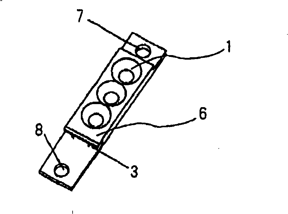
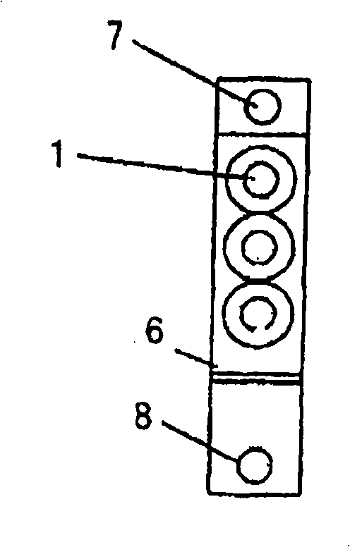
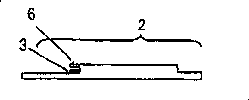
[0024] The light emitting device of this exemplary embodiment has a lead frame 9 and a resin molded part 2 such as Figures 1 to 7 shown. A plurality of light emitting elements, such as LEDs, are bonded and mounted in the lead frame 9 . Power is supplied to each light emitting element through the lead frame 9 . The resin molded part 2 not only forms the plurality of light emitting parts 1 but also covers the lead frame 9 from which the light emitting elements 1 are exposed.

[0025] Part of the lead frame 9 is exposed from one side surface of the upper portion of the resin molded part 2 . This part becomes the terminal 3 for power supply, and the bundle is inserted into the terminal 3 .

[0026] These terminals 3 are formed by bending parts of the lead frame 9 to increase the strength of the terminals 3 , and then by exposing the parts to the outside of the resin molded part 2 .

[0027] In particular, regarding the position used as the terminal 3, after bending the lead p...


PUM


Abstract

A light-emitting device of the present invention comprises a plurality of light emitting elements, a lead frame on which the light emitting elements are mounted and which supplies electric power to the light emitting elements, and a mold part which not only forms a plurality of light emitting parts (1) from which the light emitting elements are exposed, but also covers the lead frame. In addition, a part of the lead frame is exposed from the mold part as a terminal (3) for supplying power which a harness is connected, and, a portion which corresponds to the terminal for supplying power in the lead frame becomes thicker than other portions.

Description

[0001] This application is based on and claims priority from Japanese Patent Application No. 2007-105789 filed on March 13, 2007, the disclosure of which is incorporated herein by reference in its entirety. technical field [0002] The invention relates to a power supply structure for a light emitting device. Background technique [0003] A light emitting device packaged with a current lead frame is designed assuming that power is supplied by soldering the light emitting device to a printed wiring board. In particular, in the case of lighting applications requiring a large amount of light, the light emitting device is powered by the following method. [0004] That is, a plurality of light emitting devices are mounted on a printed wiring board, and the printed wiring board is attached to a lighting device to be mechanically and electrically connected. A method of supplying power to the light emitting device using the power supply wiring on the printed wiring board or the pow...

Claims


Application Information

Patent Timeline
Patent Type & Authority Applications(China)
IPC IPC(8): H01L25/00H01L25/075H01L23/495H01L23/31H01L33/62
CPCF21K9/00F21K9/30H01L33/62F21V19/001B41J2/45H01L25/0753F21Y2103/003F21V23/06F21K9/20F21Y2103/10F21Y2115/10H01L2924/0002H01L2924/00
Inventor 冲村克行
Owner NEC LIGHTING
Why Eureka
Try Eureka