
Centralized debug system and method of equipment plate card in distributed equipment

A technology of distributed equipment and equipment, applied in transmission systems, digital transmission systems, data exchange details, etc., can solve problems such as increasing software implementation costs, software design difficulty and implementation complexity, increasing equipment hardware costs, and extending development cycles. , to achieve the effect of reducing debugging cost and debugging complexity, reducing implementation cost and simplifying hardware implementation

Inactive Publication Date: 2008-10-15
NEW H3C TECH CO LTD
View PDF0 Cites 25 Cited by
  • Summary
  • Abstract
  • Description
  • Claims
  • Application Information

AI Technical Summary

Problems solved by technology

[0005] First of all, additional debugging network ports for debugging must be set on the main control board and each service board to communicate with the NP integrated development and debugging environment, which increases the cost of equipment hardware and prolongs the development cycle
[0006] Secondly, communication through the debugging network port needs to realize independent Transmission Control Protocol / Internet Protocol (TCP / IP) protocol stack and Socket port on each service board 230, to support the communication between the service board 230 and the PC through the debugging network port. Communication, which increases software implementation cost, software design difficulty and implementation complexity

Method used


Image

  • Centralized debug system and method of equipment plate card in distributed equipment
  • Centralized debug system and method of equipment plate card in distributed equipment
  • Centralized debug system and method of equipment plate card in distributed equipment

Examples


Embodiment Construction

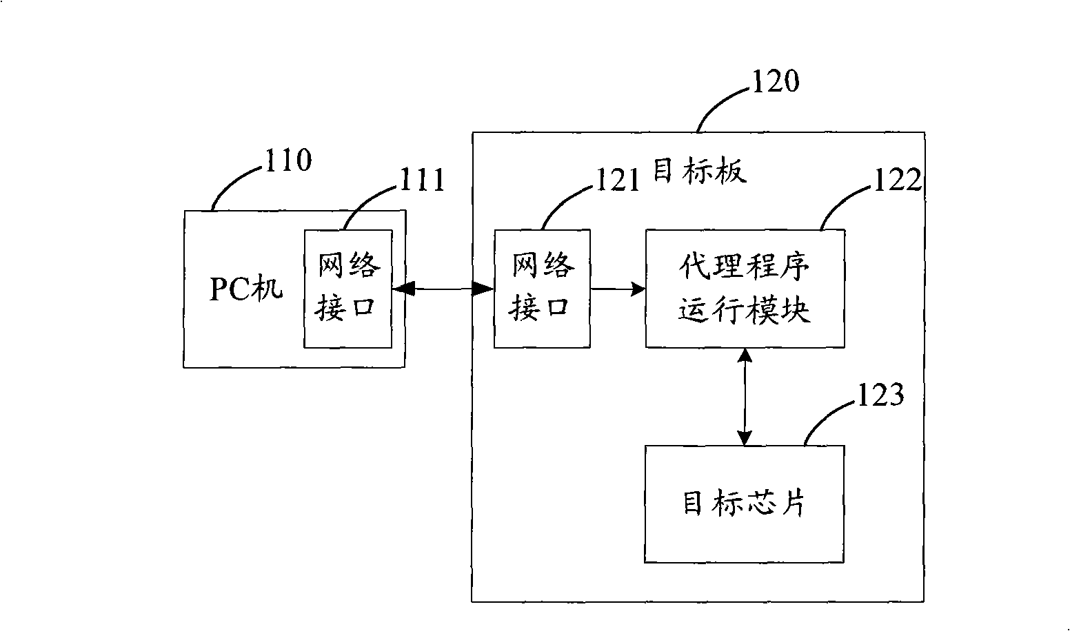
[0031] The agent program is the core of the debugging technology, and it mainly includes two functions: parsing the debugging command message and executing the debugging command. Through analysis, we know that the premise of parsing debugging command packets is to send and receive debugging command packets through the external interface, which needs to use the external interface, but does not need to use the external interface to execute debugging commands.

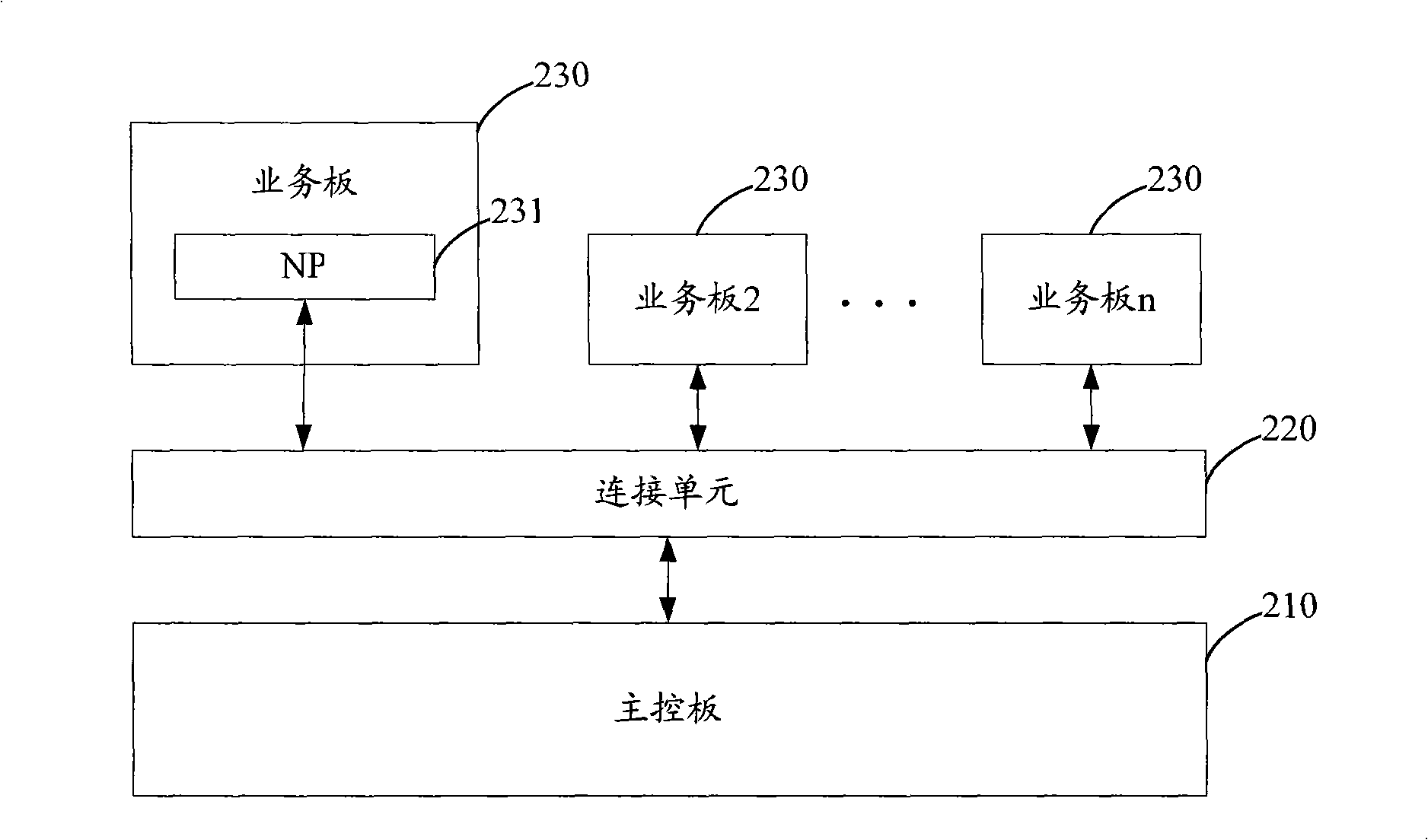
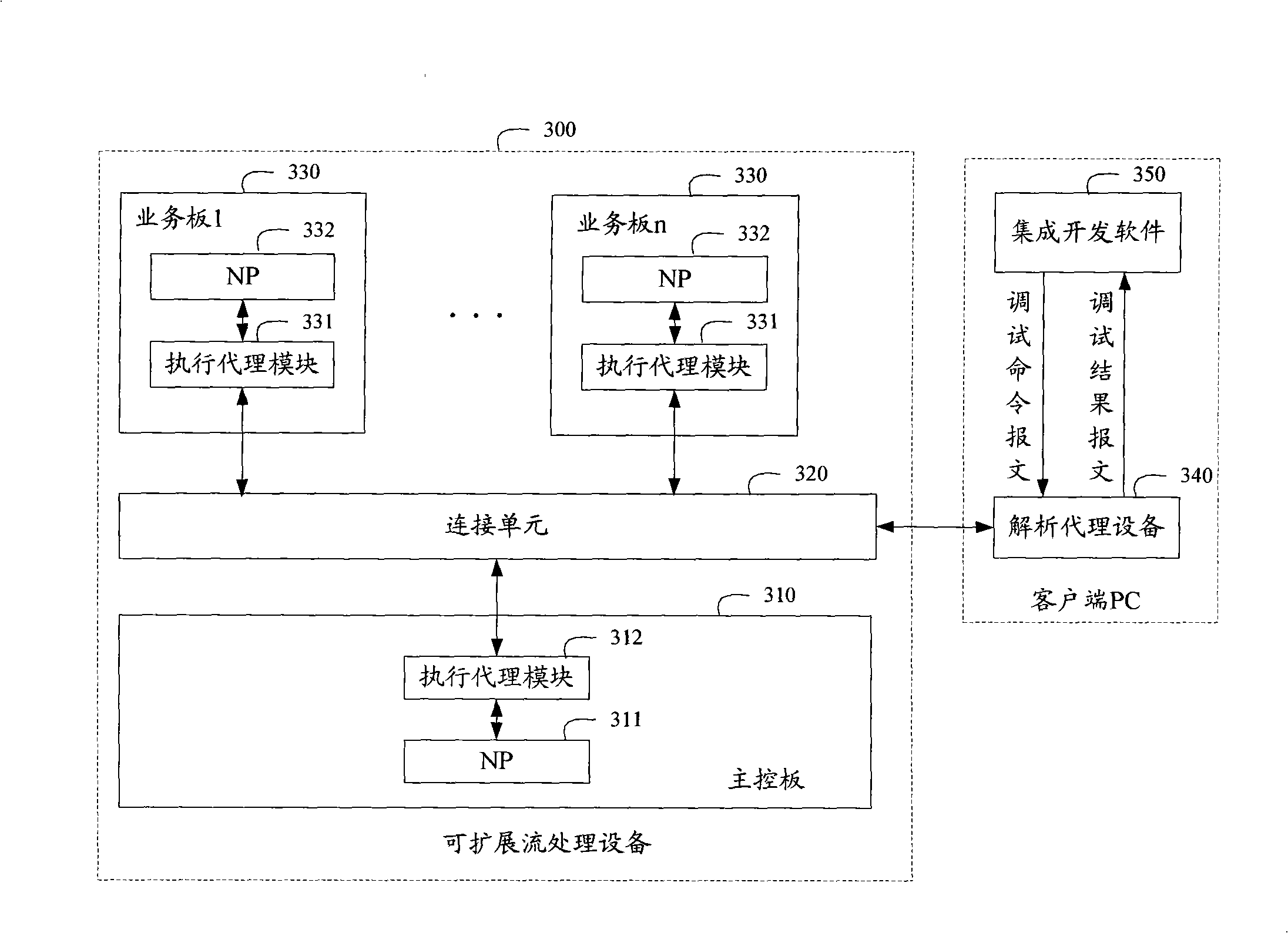
[0032] Therefore, in order to avoid setting the external interface for sending and receiving debugging command messages on the equipment boards in the distributed system, the basic idea of ​​the present invention is: retain the execution debugging command function on each equipment board to be debugged, and The function of sending, receiving and parsing the debugging command message is set in the parsing proxy device, and the parsing proxy device communicates with the device board through the connection unit in the distrib...


PUM


Abstract

The invention discloses a centralized debugging system of equipment plate cards in distributed equipment, which comprises an analysis proxy device and at least one distributed device, wherein, the distributed device comprises a connecting unit and a plurality of equipment plate cards; the analysis proxy device analyzes a debugging order from a debugging order message from outside, confirms the equipment plate cards to be debugged and transmits the debugging order to proxy implementing modules of the equipment plate cards to be debugged by the connecting unit; the proxy implementing modules transmit the received debugging order to the module to be debugged of the equipment plate cards for implementing, and transmit the implemented debugging results to the analysis surrogating module by the connecting unit, the analysis surrogating module codes the implemented results into debugging result messages for sending out. The invention also discloses a centralized debugging method of the equipment plate cards in the distributed device. By using the system and method of the invention, the implementation cost and complexity of the debugging can be reduced.

Description

technical field [0001] The invention relates to debugging technology, in particular to a centralized debugging system and a centralized debugging method for equipment boards in distributed equipment. Background technique [0002] Debugging is an essential step in the development of network equipment and its subsequent fault maintenance. In the prior art, a development kit provided by a chip manufacturer is usually used to debug a corresponding chip in the device. figure 1 It is a structural schematic diagram of a debugging system in the prior art. Such as figure 1 As shown, the system includes a PC 110 and a target board 120 . Wherein, the PC 110 runs the integrated development and debugging environment provided by the manufacturer, and is used to send debugging commands to the target board 120 through its own network interface 111 . The target board 120 specifically includes a network interface 121 , an agent program running module 122 and a target chip 123 . Wherein, ...

Claims


Application Information

Patent Timeline
IPC IPC(8): H04L12/24H04L12/02H04L12/56H04L29/08
Inventor 焦建兵邹旭东
Owner NEW H3C TECH CO LTD
Features
  • Generate Ideas
  • Intellectual Property
  • Life Sciences
  • Materials
  • Tech Scout
  • Unparalleled Data Quality
  • Higher Quality Content
  • 60% Fewer Hallucinations
Learn More