Heat radiating device

A heat dissipation device and heat sink technology, applied in cooling/ventilation/heating transformation, electrical equipment construction parts, instruments, etc., can solve the influence of the direction and position of the air outlet 521, and cannot flexibly adjust the direction and position of the airflow at the air outlet 521 , It is difficult to meet the problems of the shape design of the casing, so as to achieve the effect of convenient shape design

Inactive Publication Date: 2008-10-15
FU ZHUN PRECISION IND SHENZHEN +1
View PDF0 Cites 4 Cited by
  • Summary
  • Abstract
  • Description
  • Claims
  • Application Information

AI Technical Summary

Problems solved by technology

[0004] However, since the air outlet 521 of the centrifugal fan 52 is usually adjacent to the side wall of the casing and communicates with the air outlet provided on the side wall, the direction and position of the air outlet 521 will also be affected by the shape design of the casing.
The heat sink 54 in the existing heat dissipation device 50 has a one-piece rectangular parallelepiped structure, which cannot flexibly adjust the direction and position of the airflow at the air outlet 521, so it is difficult to meet the requirements of the casing shape design

Method used


Image

  • Heat radiating device
  • Heat radiating device
  • Heat radiating device

Examples


Embodiment Construction

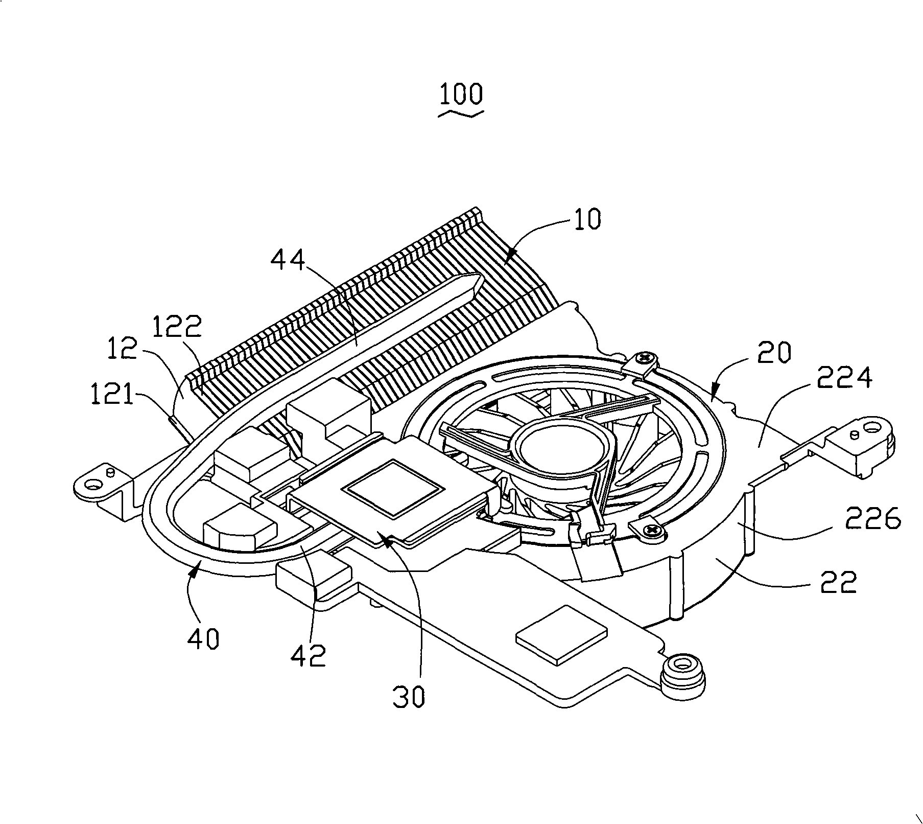
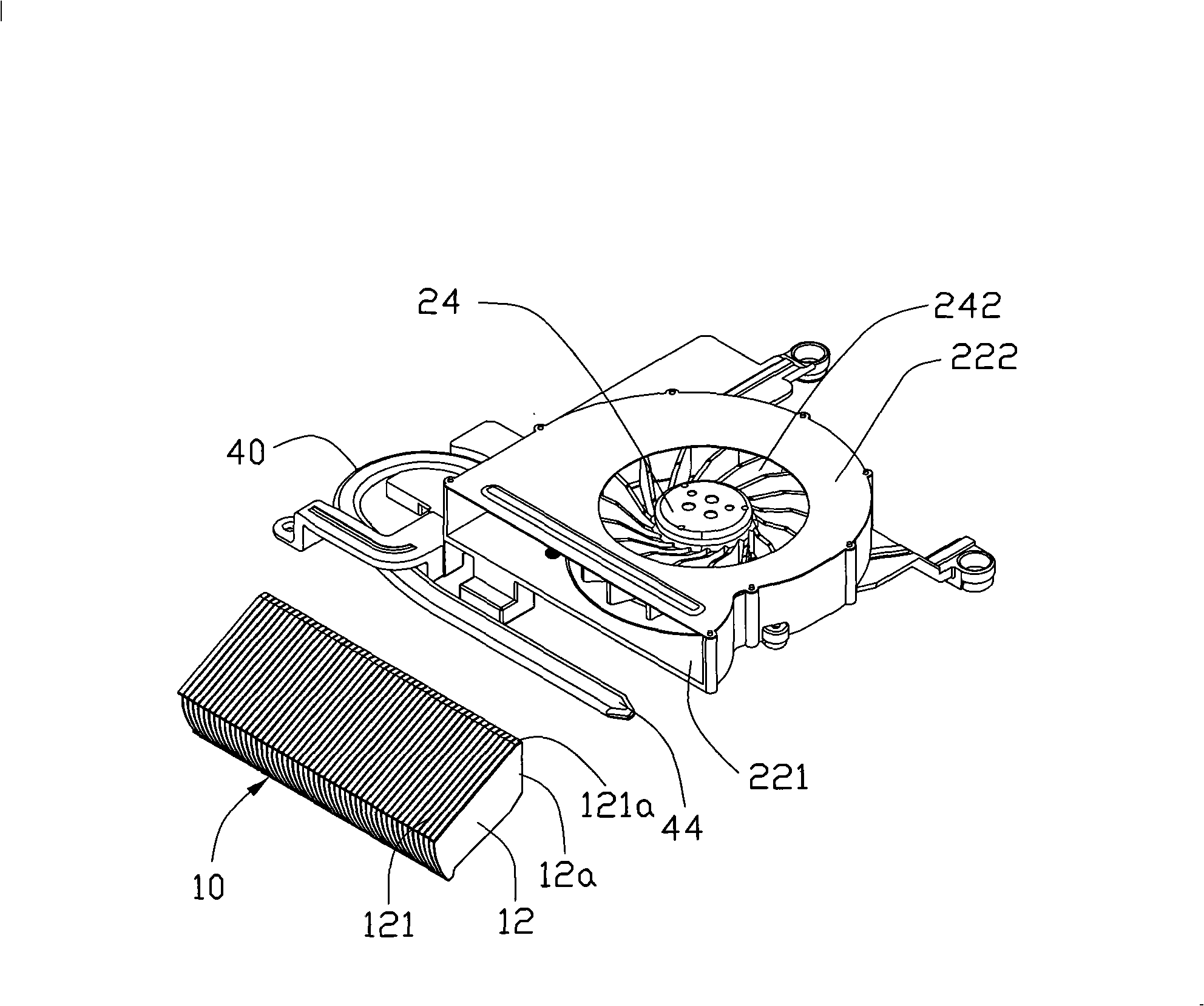
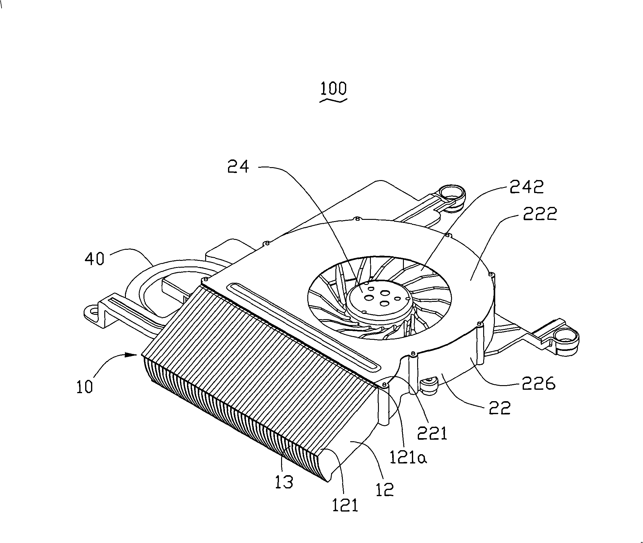
[0016] figure 1 Shown is a three-dimensional assembly view of the first embodiment of the heat dissipation device of the present invention along a first viewing angle. The heat dissipation device 100 can be installed in the casing (not shown) of electronic products such as notebook computers or all-in-one liquid crystal computers (LCD PCs). , which includes a radiator 10 , a centrifugal fan 20 , a base 30 and a heat pipe 40 . The base 30 is thermally connected to a heat-generating electronic component (not shown) located in the casing, one end of the heat pipe 40 is thermally connected to the base 30, and the other end is attached to the heat sink 10, and the base The heat on the seat 30 is transferred to the heat sink 10 . The centrifugal fan 20 is used to forcibly dissipate heat from the radiator 10 .

[0017] Please refer to Figure 1 to Figure 3 , the centrifugal fan 20 includes a casing 22 , a stator (not shown) and a rotor 24 , the stator and the rotor 24 are install...


PUM


Abstract

The invention provides a heat dissipation device used for emitting heat caused by heating electronic elements and comprises a centrifugal fan and a radiator. The radiator comprises a plurality of flow channels and the centrifugal fan is used for generating cooling draught to carry out the compulsory heat dissipation for the radiator. The centrifugal fan is provided with an air outlet and the radiator is aslant arranged corresponding to the air outlet. By the slantwise arrangement of the radiator, the direction and the position of the cooling draught in the air outlet can be flexibly adjusted, thus being convenient for the shape design of a device case.

Description

technical field [0001] The invention relates to a heat dissipation device, in particular to a heat dissipation device suitable for heating electronic components. Background technique [0002] At present, with the rapid development of the computer industry, more and more heat is generated by heat-generating electronic components such as micro-processing chips, and the problem of heat dissipation has been paid more and more attention by people. In notebook computers or more advanced all-in-one liquid crystal computers (LCD This is especially true in compact electronic products such as PCs. Generally speaking, the structural design of the heat dissipation device should meet the requirements of the internal space of the electronic product. However, the appearance design of the case of a notebook computer or an all-in-one LCD computer is an important factor that attracts consumers. With the continuous refurbishment of the shape of the casing and the development towards lightnes...

Claims


Application Information

Patent Timeline
Patent Type & Authority Applications(China)
IPC IPC(8): H05K7/20H01L23/467H01L23/367H01L23/34G06F1/20
CPCH05K7/20154
Inventor HONG RUIWEN
Owner FU ZHUN PRECISION IND SHENZHEN
Why Eureka
Try Eureka