

Pressure control device
A pressure control and fluid technology, applied in the direction of control valves, valve devices, spring devices, etc., to suppress fuel pulsation, prevent abnormal noise, and prevent functional deterioration.
Inactive Publication Date: 2008-10-15
MITSUBA CORP +2
View PDF3 Cites 6 Cited by
- Summary
- Abstract
- Description
- Claims
- Application Information
AI Technical Summary
Problems solved by technology
Therefore, the specifications that pulsation may occur in the region below 20 (l / h) cannot be directly used in actual vehicles, and improvement is required
Method used
View moreImage
Smart ImageViewing Examples

Examples
Embodiment 1
Embodiment 2
Embodiment 3
Login to View More PUM
 Abstract
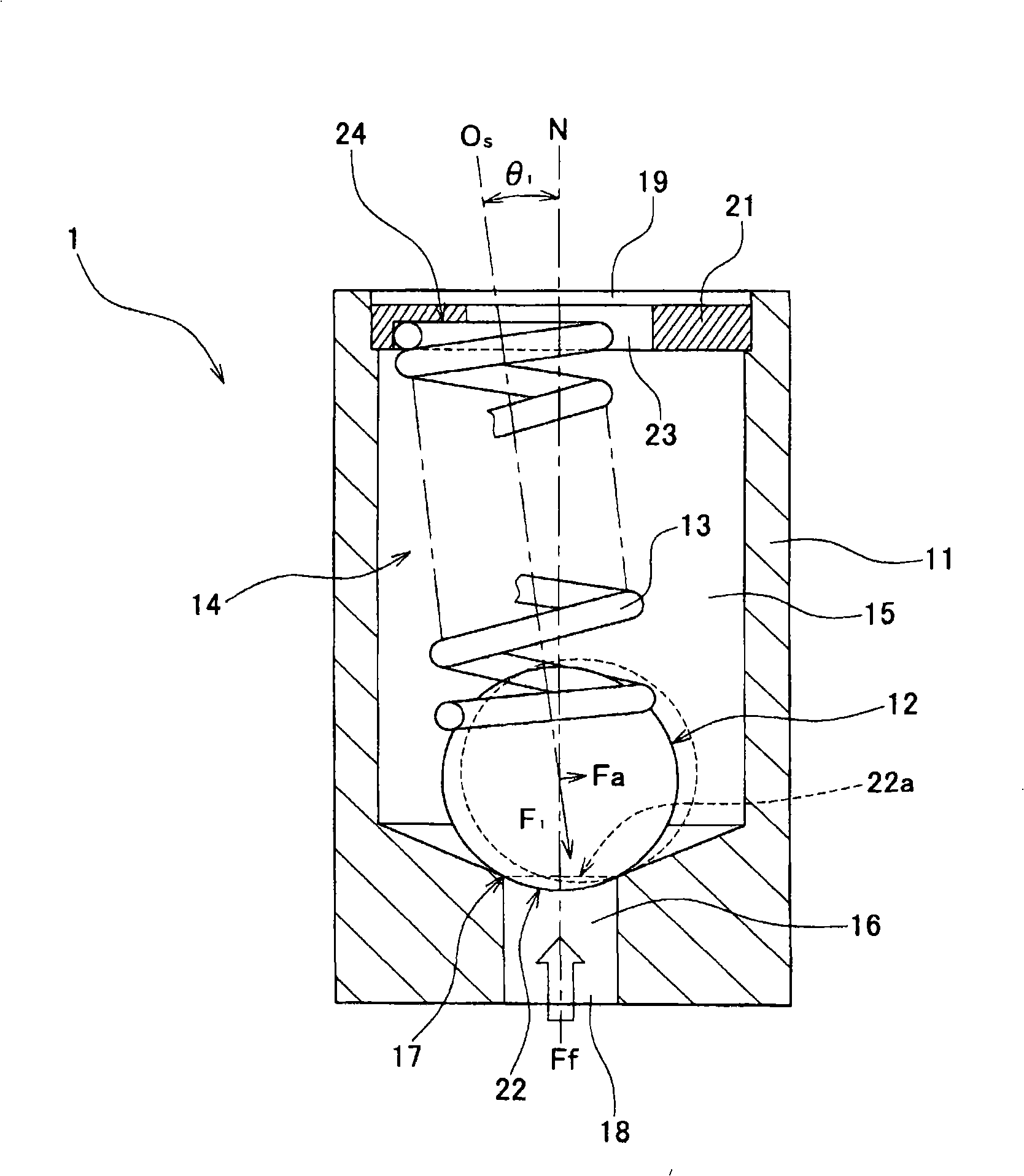
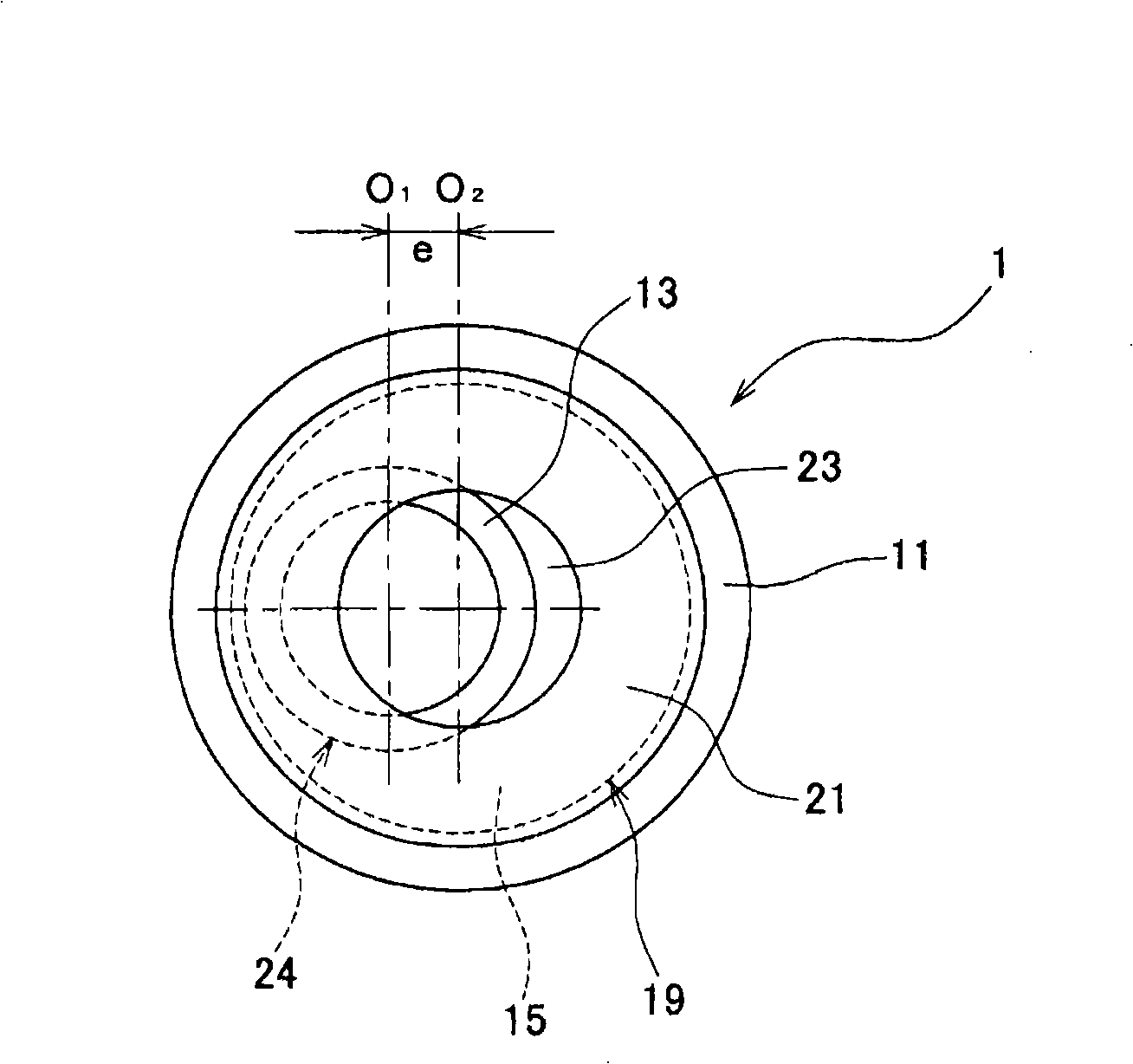
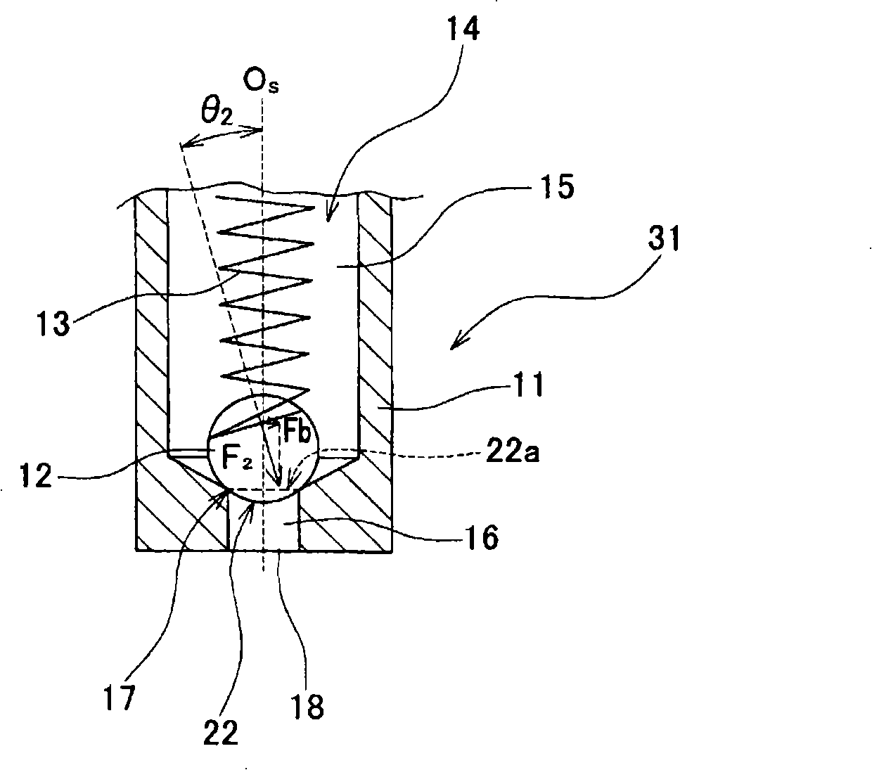
A pressure control device in which pulsation is reduced and an occurrence of noise etc. is prevented. A pressure regulator (1) has a housing (11) having a fuel inlet (18), a fuel outlet (19), and a fuel path (14) for communicating the fuel inlet and fuel outlet, a ball (12) placed in the fuel path (14), a seal section (17) having an opening (22) communicating with the fuel inlet (18) and closing the fuel path (14) when an edge (22a) of the opening (22) is in contact with the ball (12), and a valve spring (13) for urging the ball (12) toward the seal section (17). The valve spring (13) is placed inclined relative to a line (N) normal to a cross-section of the opening (22), and valve body pressing force is different depending on a portion of the opening section (22). When the valve is opened, the ball (12) moves positioned to the right side in the figure, and the left side in the figure of the opening (22) is opened.
Description
pressure control device technical field The present invention relates to a pressure control device for adjusting fluid pressure, in particular to a pressure control device for a fuel supply system of an engine. Background technique In fluid supply systems such as fuel supply systems and hydraulic circuits of automobiles, various pressure control devices are used to prevent excessive fluid pressure. As such a pressure control device, a pressure regulator using a diaphragm, a check valve, and the like are known. For example, Japanese Patent Application Laid-Open No. 9-166059 (Patent Document 1) discloses a fuel supply device equipped with a check valve type pressure regulator. In the pressure regulator of Patent Document 1, the spool (sleeve) is held by a compression coil spring. Then, the opening and closing of the valve is controlled by the movement of the spool, and the pressure of the fuel discharged from the fuel supply device (fuel pressure) is adjusted. Also, Japan...
Claims
Login to View More Application Information
Patent Timeline
 Patent Type & AuthorityApplications(China)
IPC IPC(8): F16K17/04F02M55/02F02M37/00
CPCF02M37/0029F02M69/54F16K15/044F16K17/0406F16K17/0466F16K2200/305
Inventor下川真辉鵤木孝夫小野智弘本间文司早坂敦史
OwnerMITSUBA CORP