Quick changing bending machining pad pillow

A technology of bending and cushioning, applied in metal processing equipment, forming tools, manufacturing tools, etc., can solve the problems of large changeover time and labor costs, and achieve the effect of reducing capital equipment costs and reducing changeover time

Active Publication Date: 2008-10-22
GM GLOBAL TECH OPERATIONS LLC
View PDF0 Cites 20 Cited by
  • Summary
  • Abstract
  • Description
  • Claims
  • Application Information

AI Technical Summary

Problems solved by technology

However, even with this equipment, significant changeover time and labor costs remain

Method used


Image

  • Quick changing bending machining pad pillow
  • Quick changing bending machining pad pillow
  • Quick changing bending machining pad pillow

Examples


Embodiment Construction

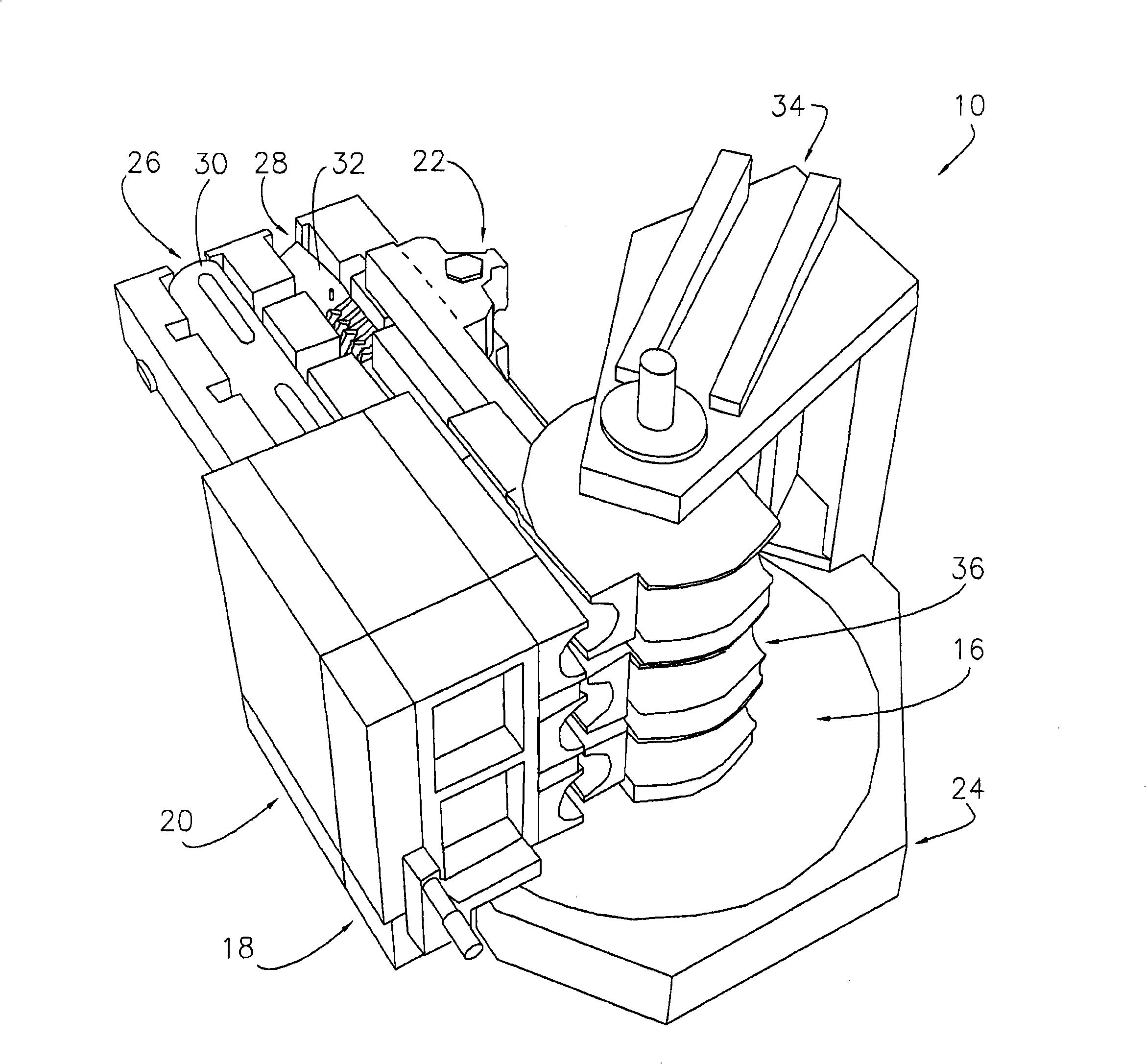
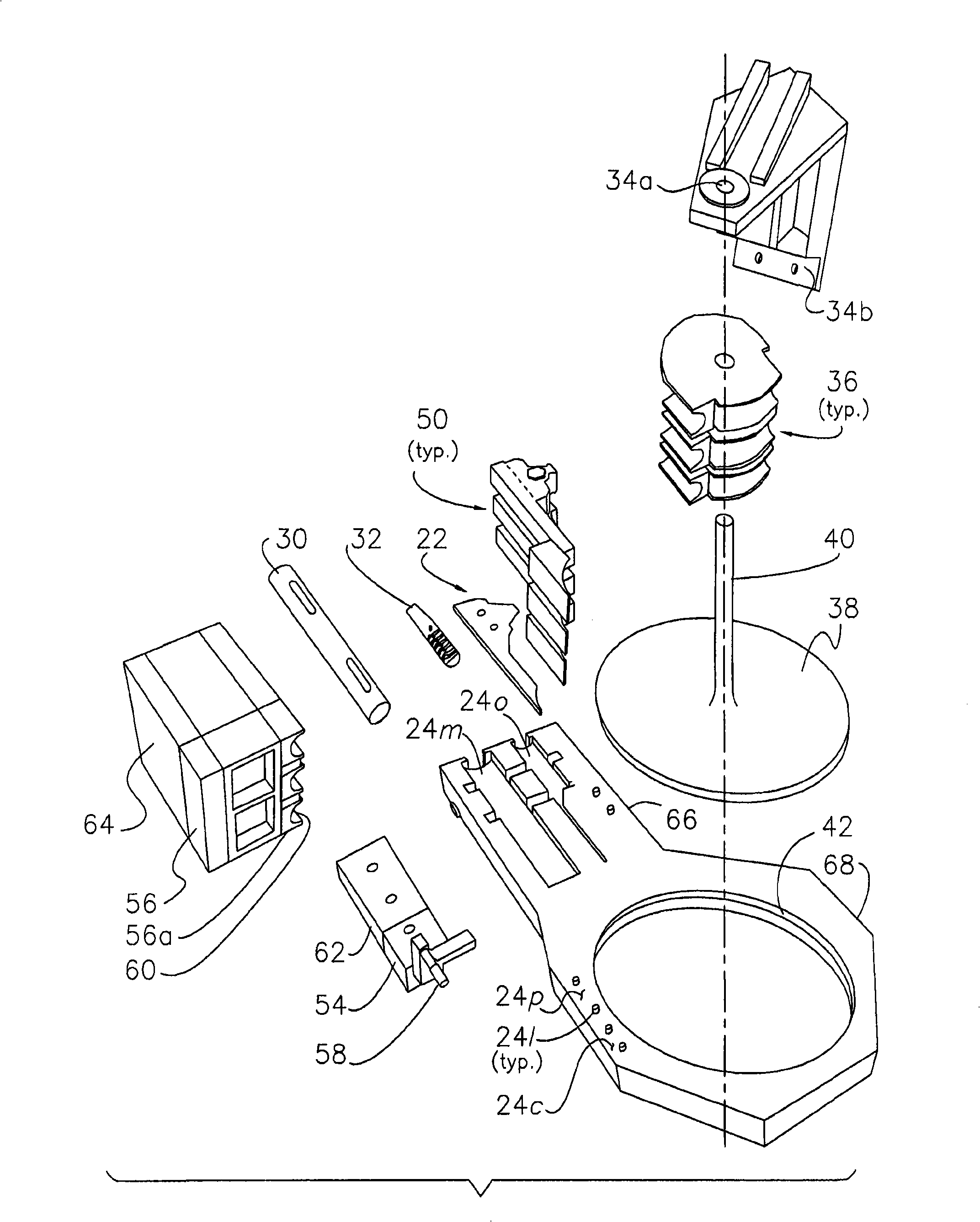
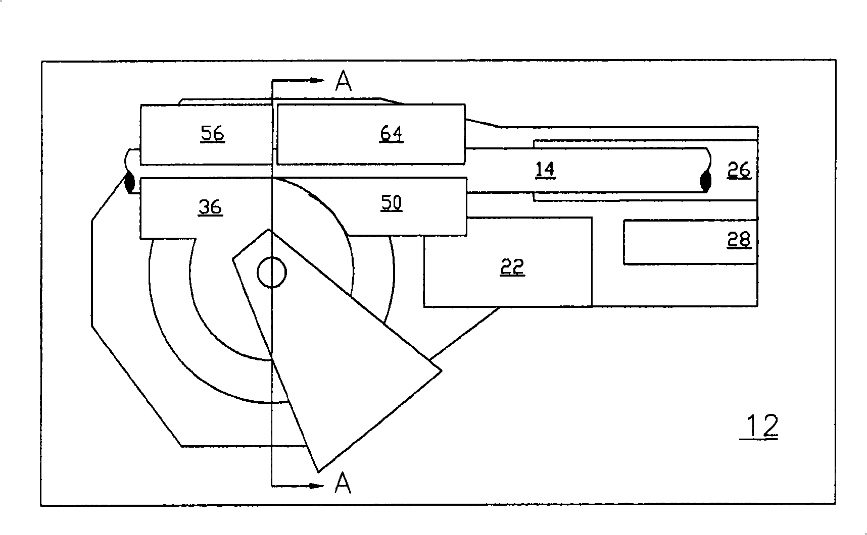
[0011] Such as Figure 1-12 As shown, the present invention relates to a novel bender assembly 10, 100 adapted to be used with a rotary drawing bender or bender 12 ( image 3 ), the rotary stretch pipe bender or bender 12 is, for example, a computer numerically controlled (CNC) bender, a numerically controlled (NC) bender, or a conventional type bender. As is known in the art, the function of the rotary stretch bender 12 is to compress the tube 14 against the bend profile such that the point at which the bend occurs is fixed and the profile is tangent to the entry line of the tube 14 (cf. image 3 with 3a and Figure 10 with 10a ). Typically, to achieve this, bender 12 rotates the bending dies and uses a series of other dies to hold or grip the tube and exert pressure on the tube. Bending machine 12 may use manual, machine-assisted manual, electric, hydraulic, or electro-hydraulic systems to achieve rotational displacement. While the preferred assembly 10, 100 is describ...


PUM


Abstract

A tube bending assembly adapted for use with a rotary draw bender, and preferably including a bend die mounting unit for securing a plurality of stacked bend dies drivenly coupled to the bender, a bend die tower unit for structurally supporting the bend die mounting unit, a wiper die mounting unit for securing a wiper die adjacent a selected bend die, a clamp die mounting unit for positioning and securing a clamp die, a pressure die mounting unit for securing a pressure die adjacent the clamp die, a mandrel saddle unit for positioning and enabling the utilization of a mandrel assembly, a collet saddle unit for positioning and enabling the utilization of a collet, and a bolster unit that interconnects the units, so as to present an integrated assembly capable of concurrent disconnection from and connection to the bender, and thereby reducing the tool set change-over period.

Description

technical field [0001] The present invention generally relates to pipe benders and pipe bending apparatus. More particularly, the present invention relates to assemblies configured to facilitate proper positioning, interconnection, and retention of an entire bending apparatus for quick connection to, or quick disconnection from, a pipe bender. open or separate. Background technique [0002] Traditional tube benders or bending machines mainly use compression, extrusion and rotational stretching to bend tubes along circular arcs. These machines and methods are commonly used in a variety of industrial applications including automotive, aircraft component and equipment / pipe manufacturing. These machines typically include a series of dies and drive mechanisms that work in conjunction to exert pressure on the tube to bend it into a predetermined form. More specifically, for rotational stretch bending, the bending die is positioned adjacent to the desired cut plane of the tube. ...

Claims


Application Information

Patent Timeline
Patent Type & Authority Applications(China)
IPC IPC(8): B21D7/024B21D37/14B21D37/12
CPCB21D7/024
Inventor D·T·沃伦豪斯A·M·马丁内斯M·H·洛弗尔M·A·克莱恩D·R·弗理德尔
Owner GM GLOBAL TECH OPERATIONS LLC
Why Eureka
Try Eureka