Plate valve for tensioining systems for traction means

A tensioning system and tool technology, applied in the direction of valve devices, control valves, function valve types, etc., can solve the problems affecting the installation space of the hydraulic valve of the tensioning device, large structural space, etc., to achieve reduced quality, large pressure action area, The effect of optimal working ability

Inactive Publication Date: 2008-10-22
SCHAEFFLER TECH AG & CO KG
View PDF1 Cites 3 Cited by
  • Summary
  • Abstract
  • Description
  • Claims
  • Application Information

AI Technical Summary

Problems solved by technology

[0004] The plate valves known previously have in common the requirement of a considerable construction space, which directly affects the installation space required for the hydraulic valve of the tensioning device

Method used


Image

  • Plate valve for tensioining systems for traction means
  • Plate valve for tensioining systems for traction means

Examples


Embodiment Construction

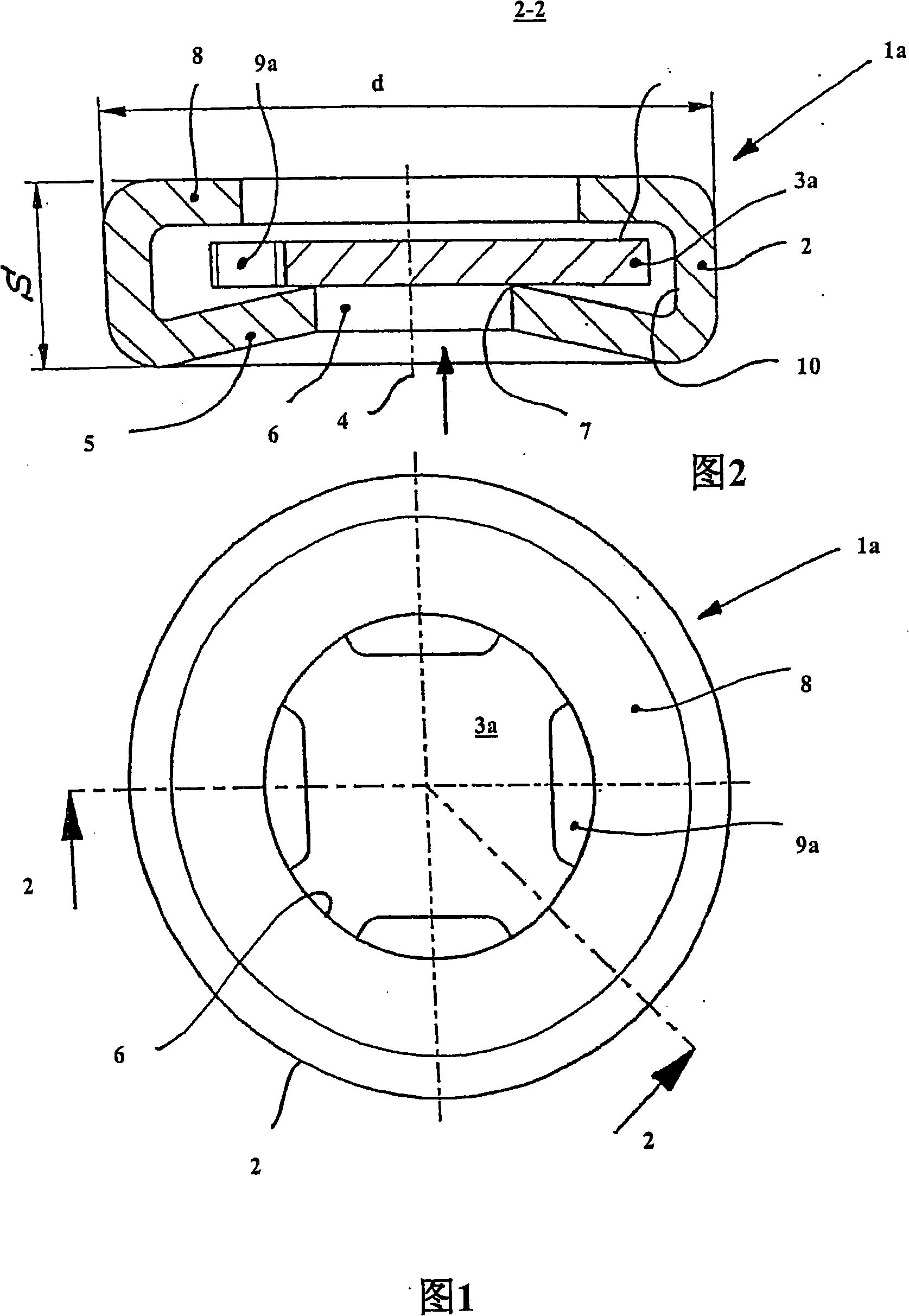
[0024] 1 and 2 show a rotationally symmetrical non-return valve 1a designed as a plate valve. This structure comprises a housing formed as a cage 2 into which a valve body 3a formed as a disk is inserted with play. The cage 2 produced without cutting comprises a base 5 that tapers conically towards the longitudinal axis 4 . An opening 6 is formed in the center of the bottom 5 , on the inner side of which the valve body 3 a is supported in a sealing manner on the edge region forming the valve seat 7 . The cage 2 is distanced from the bottom 5 by a continuous rim 8 with a right-angle chamfer, which prevents loss of the valve body 3a and at the same time limits the lift. FIG. 2 shows the non-return valve 1 a in the closed position, in which the valve body 3 a rests tightly against the valve seat 7 . When the check valve 1a is loaded with hydraulic fluid in the direction of the arrow, the valve body 3a moves to the inner side of the rim 8 . In this respect, hydraulic fluid can ...


PUM


Abstract

A case in which a vehicular power transmitting apparatus is stored, has: an annular support portion which surrounds an outer periphery of a planetary gear set and supports a fixed element from among a plurality of gears and a carrier of the planetary gear set; an outer peripheral wall portion that surrounds the annular support portion; a flange portion that forms a mounting surface on an outer portion of the outer peripheral wall portion; and a dividing wall portion which extends to the outside from the annular support portion toward the outer peripheral wall portion and the flange portion, and which forms the flange portion and the mounting surface and divides spaces within the case. A joining portion, in which a fastening hole to which the fastening member is joined and whose axis passes through the dividing wall portion is formed, is integrally formed with the dividing wall portion.

Description

technical field [0001] The invention relates to a plate valve of a hydraulic tensioning system, which cooperates with a traction tool of a traction tool transmission mechanism through a tension frame. The tensioning system comprises a housing in which a piston is guided, which is spring-loaded and delimits a pressure chamber filled with hydraulic fluid. The hydraulic fluid flows into the pressure chamber through a non-return valve distributed in the housing. Background technique [0002] EP 0 919 744 A1 discloses a tensioning system comprising a disk-shaped valve body as a non-return valve. In this respect, the valve body is connected to a tappet which is arranged in the inner filling sleeve of the tensioning piston. The tappet is guided within the sleeve by the engagement of a metal ring that exerts a radial force so that the tappet moves under friction. For this frictional connection between the plate valve body and the tensioning piston, there is a direct interlinkage ...

Claims


Application Information

Patent Timeline
Patent Type & Authority Applications(China)
IPC IPC(8): F16K15/08F16H7/08
CPCF16H2007/0859F16H7/0836F16H7/08
Inventor 罗曼·克恩
Owner SCHAEFFLER TECH AG & CO KG
Why Eureka
Try Eureka