Pattern checking device and pattern checking mehtod

A technology for inspection devices and inspection methods, which is applied in the direction of measuring devices, instruments, measuring electronics, etc., and can solve the problems of being unable to detect whether there are pits or not

Inactive Publication Date: 2008-10-22
USHIO DENKI KK
View PDF2 Cites 9 Cited by
  • Summary
  • Abstract
  • Description
  • Claims
  • Application Information

AI Technical Summary

Problems solved by technology

Therefore, the surface of the wiring pattern becomes the backlight of the wi

Method used


Image

  • Pattern checking device and pattern checking mehtod
  • Pattern checking device and pattern checking mehtod
  • Pattern checking device and pattern checking mehtod

Examples


Embodiment Construction

[0060] Embodiments of the present invention will be described using FIGS. 1 to 10 .

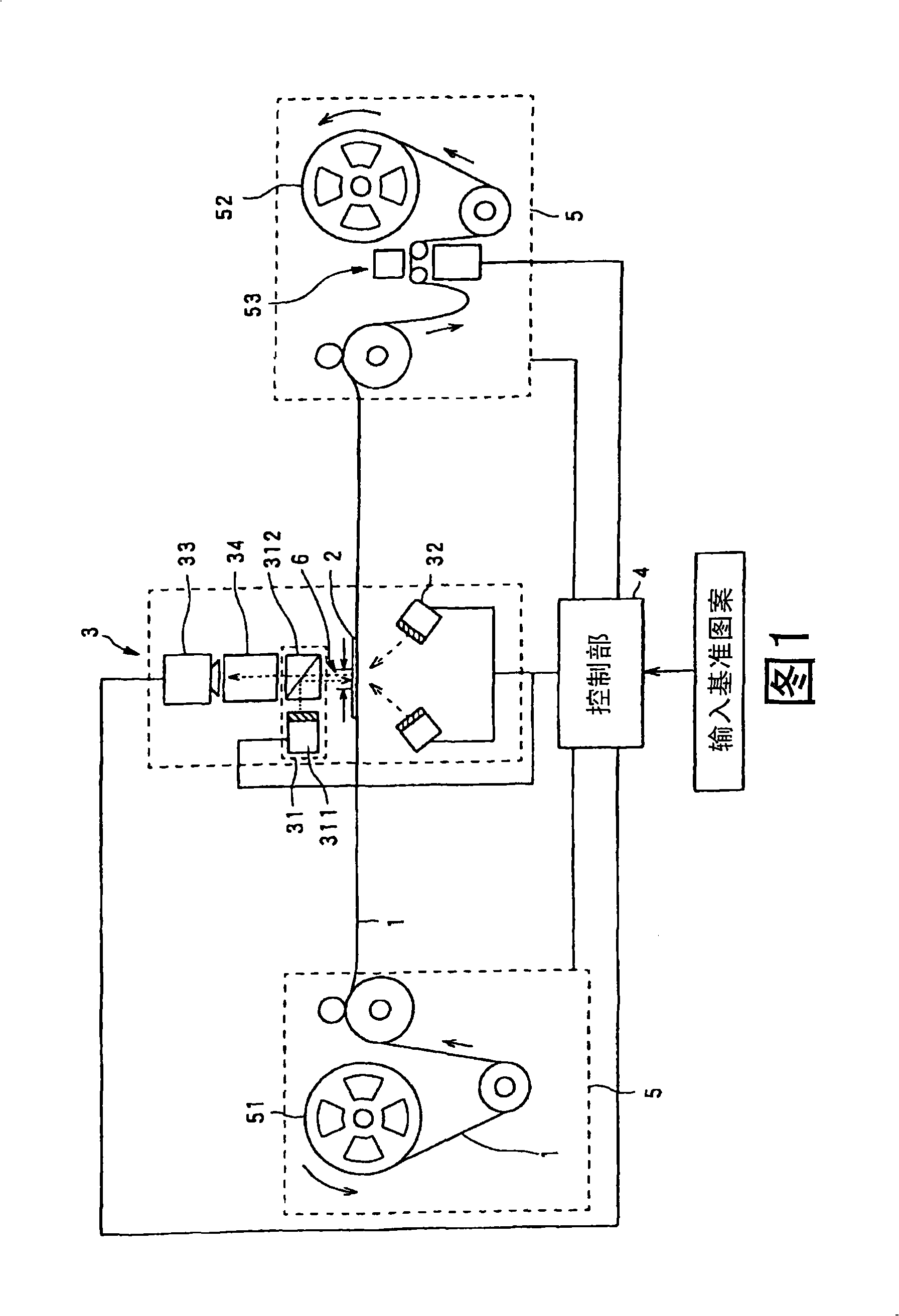
[0061] FIG. 1 is a block diagram showing the overall configuration of a pattern inspection device according to the invention of the present embodiment.

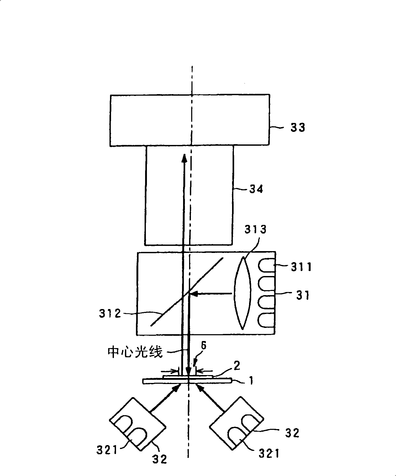
[0062] In FIG. 1, 1 is a light-transmissive substrate such as a TAB tape made of polyimide (resin), etc., 2 is a pattern such as a wiring pattern formed on the substrate 1 and made of copper, etc., 3 is an inspection part, and 31 It is a reflected illumination unit (first illumination unit) that irradiates illumination light passing through the center of the beam center of the illumination light from the side on which the pattern 2 on the substrate 1 is substantially perpendicular to the inspection area of ​​the substrate 1 (first illumination unit), 311 is a light source, 312 is a half mirror, and 32 is on the opposite side to the side where the pattern 2 on the substrate 1 is formed, from the area illuminated by the first lighting unit on ...


PUM


Abstract

A pattern detecting device uses indirect illumination light and transmission illumination light to differentiate the concave pit and bulge generated at surface of the pattern and only detects the concave pit as the badness. The pattern detecting device judges whether the pattern is qualified according to the camera image of the illumination light for illuminating the pattern (2) formed on a light transmission substrate (1); the pattern detecting device comprises a first lighting unit (31) for irradiating the illumination light almost vertical to the substrate relative to the central light; a second lighting unit (32) for irradiating illumination light to the substrate from the detecting area (6) arranged at back of the substrate to the area of substrate mapped on the normal direction; a camera unit (33) arranged on the direction the same with the illumination direction of the first lighting unit (31); and a control unit (4) for controlling the first lighting unit and the second lighting unit (32). The control unit irradiates the first lighting unit and the second lighting unit; the camera unit shoots the irradiated pattern.

Description

technical field [0001] The present invention relates to a pattern inspection device and a pattern inspection method, and in particular to inspection of whether or not pits (pits) are formed on the surface of a pattern such as a wiring pattern formed on a light-transmitting substrate such as a TAB (Tape Automated Bonding) tape An inspection device and a pattern inspection method. Background technique [0002] Conventionally, in inspection of wiring patterns, methods and devices for preventing erroneous detection by distinguishing dirt (foreign matter) adhering to the surface or back of a substrate from defects in wiring patterns are disclosed in, for example, Patent Document 1 or Patent Document 2. The above publication describes a comparison of an reflected illumination image obtained by imaging reflected illumination light from a substrate on which a wiring pattern is formed, and a transmitted illumination image obtained by imaging transmitted illumination light from the ba...

Claims


Application Information

Patent Timeline
IPC IPC(8): G01N21/956G01R31/00
CPCH01L2924/0002H01L2924/00H01L22/00
Inventor 野本宪太郎松田僚三林宏树
Owner USHIO DENKI KK
Why Eureka
Try Eureka