Lens module group assembling system and method of use thereof

A technology for assembling systems and lens modules, applied in installation, optics, instruments, etc., can solve problems such as difficult lens barrels, difficult assembly, and large manpower consumption, and achieve the effect of easy assembly

Inactive Publication Date: 2008-10-22
HONG FU JIN PRECISION IND (SHENZHEN) CO LTD +1
0 Cites 9 Cited by

AI-Extracted Technical Summary

Problems solved by technology

The assembly of various components in the lens module, such as the lens barrel (for the built-in lens) and a base such as the lens holder (for the built-in image sensor), is also becoming more and more difficult, especially when manually assembled, the operator's fingers Or t...

Method used

Seen from the above steps, the lens module assembly system 100 first uses a base alignment device 10 to align the base 300, and uses a lens barrel assembly device 20 to absorb and guide the lens barrel 200, Then the lens barrel assembly device 20 moves to the top of the center ...

Abstract

The invention relates to a lens module assembly system used for assembling lens barrels and bases. The assembly system comprises a base contraposition device, a suction nozzle, at least one centering component, a moving arm and a driving device, wherein the base contraposition device comprises a platform for bearing and placing a base, a first contraposition block and a second contraposition block which respectively have an inner wall structure matched with the outer wall of the base; the second contraposition block can move relative to the first contraposition block, so as to push the base to a preset position between the first contraposition block and the second contraposition block; the suction nozzle is provided with at least one air exhaust through hole and is used for adsorbing a lens barrel; the centering component is used for straightening the lens barrel; the moving arm is used for driving the suction nozzle to be displaced to be above the center of the preset position between the first contraposition block and the second contraposition block of the contraposition device and to be moved down, so as to ensure that the lens barrel is in alignment with the base; the driving device is used for driving the suction nozzle to rotate, so as to rotate the lens barrel to be in threaded connection with the base.

Application Domain

Technology Topic

Image

  • Lens module group assembling system and method of use thereof
  • Lens module group assembling system and method of use thereof
  • Lens module group assembling system and method of use thereof

Examples

  • Experimental program(1)

Example Embodiment

[0011] The lens module assembly system provided by the present invention and its usage method will be described in further detail below in conjunction with the accompanying drawings.
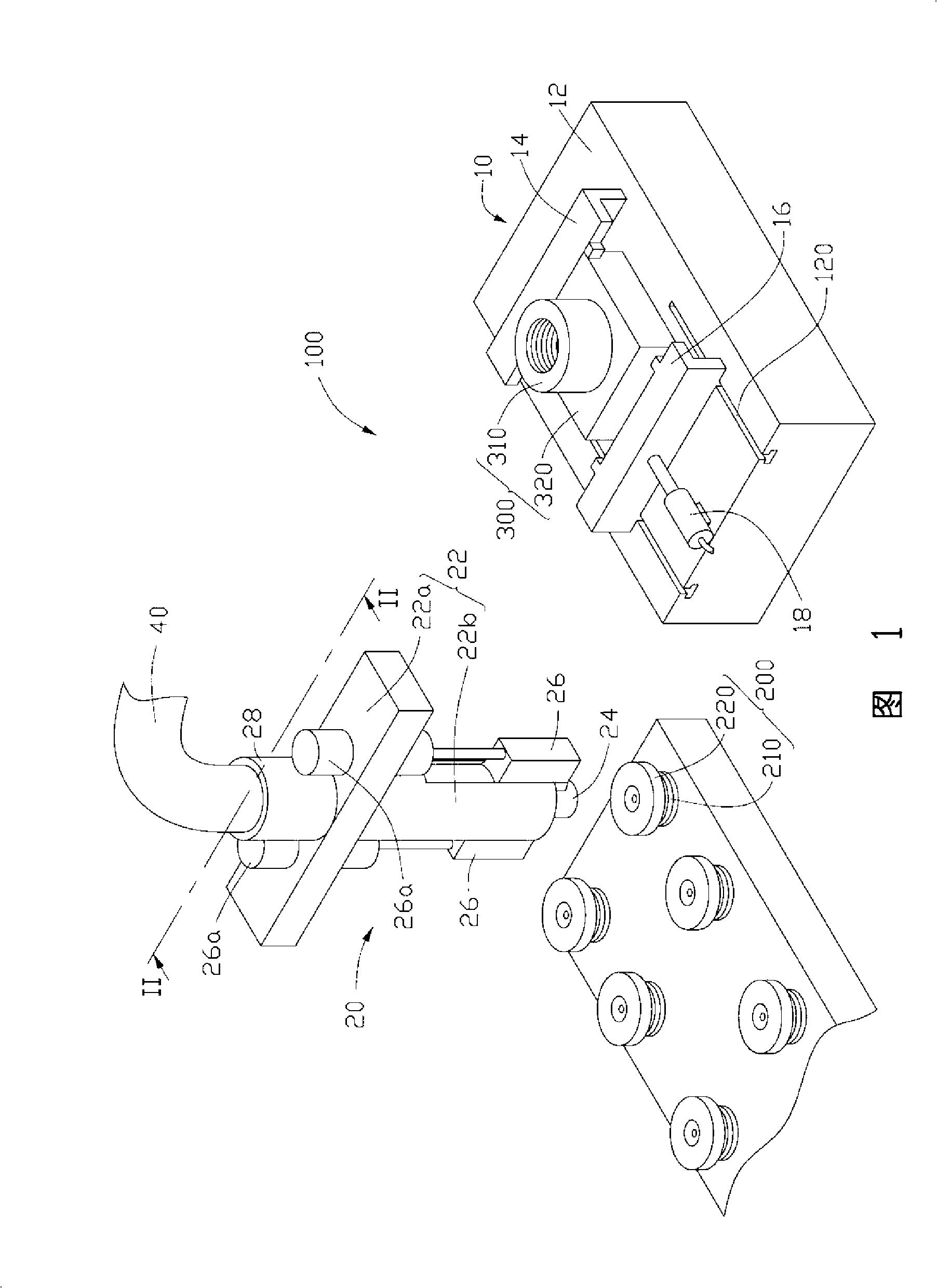
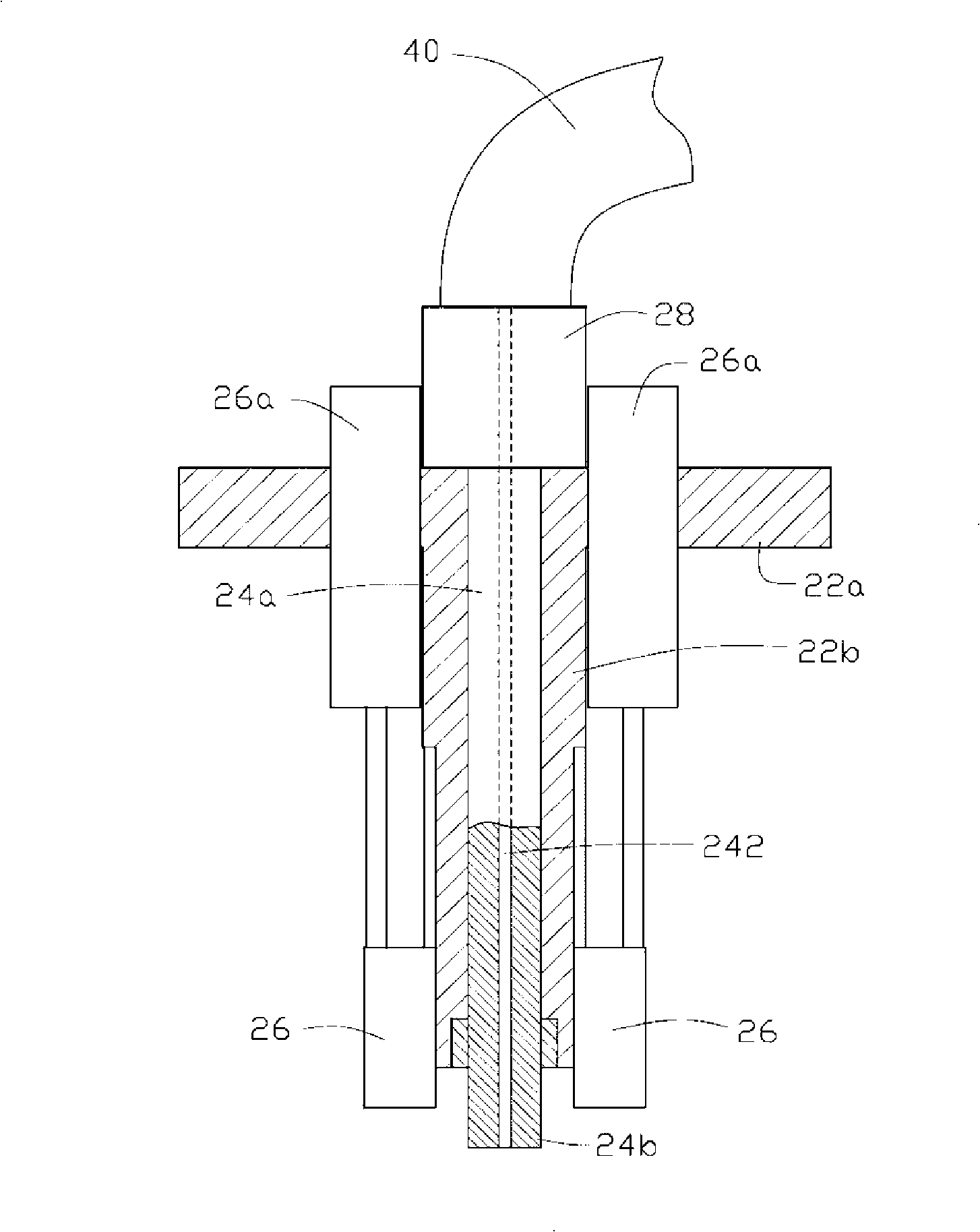
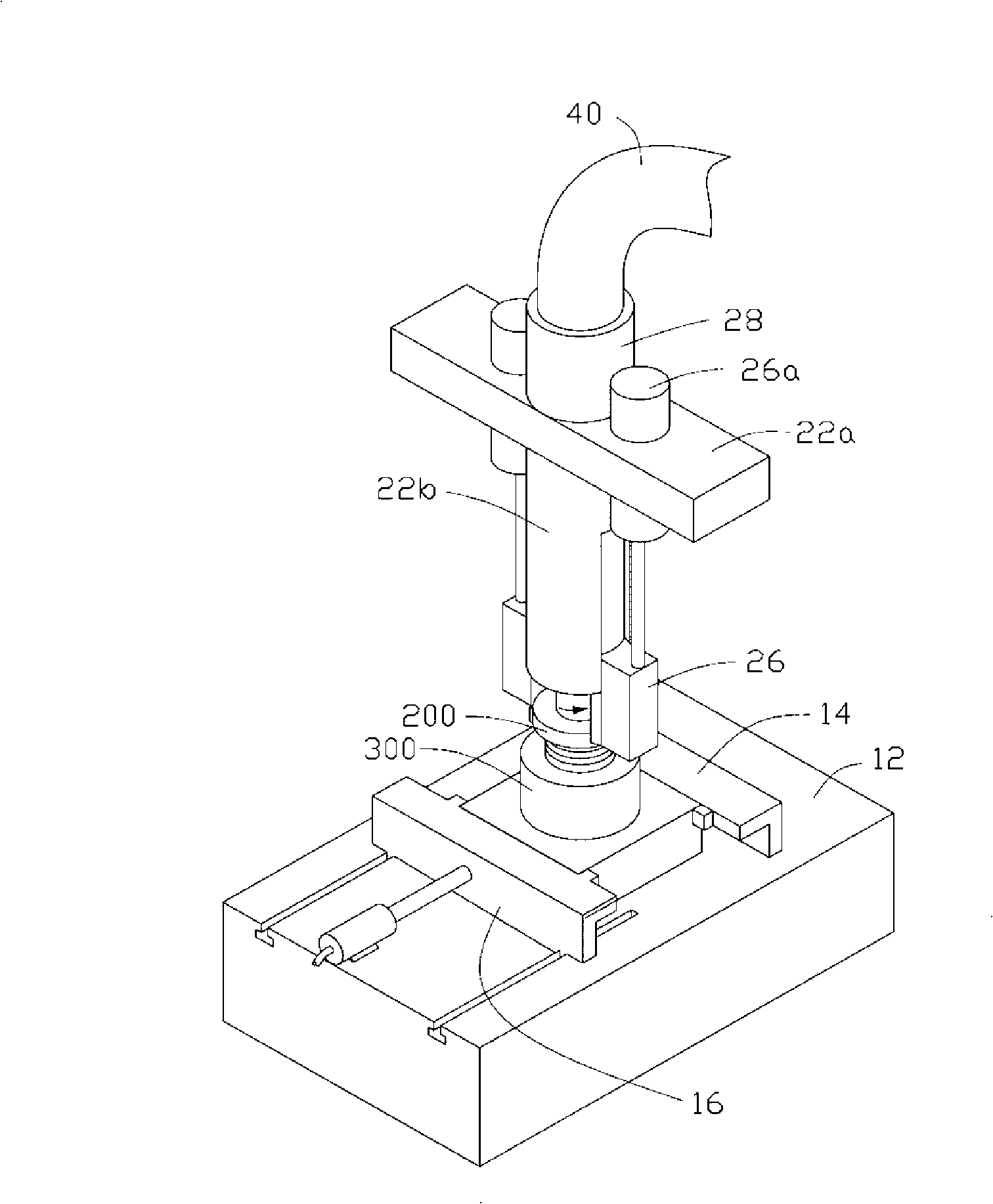
[0012] Please also refer to Figure 1 to image 3 , the lens module assembly system 100 provided by the embodiment of the present invention is used to assemble the lens barrel 200 and the base 300, which includes: a base alignment device 10 for aligning the base 300, and a mirror The barrel assembly device 20 is used for assembling the lens barrel 200 to the base 300 .
[0013] The lens barrel 200 includes a barrel body 210 and a retainer 220 located at the end of the barrel body 210 . The outer wall of the barrel body 210 is provided with an annular external thread, and the shape of the retainer 220 is circular. The lens barrel 200 may be pre-assembled with optical components such as lenses, diaphragms, and filters. The base 300 includes a cylindrical portion 310 and a frame portion 320, the inner wall of the cylindrical portion 310 is provided with an annular internal thread to connect with the annular external thread of the lens barrel 200, the square frame The shaped part 320 can be used to accommodate an image sensor (not shown).
[0014] The base alignment device 10 includes a platform 12 for accommodating the base 300 , and a first alignment block 14 and a second alignment block 16 oppositely disposed on the platform 12 . The platform 12 defines two slide slots 120 on one side of the second alignment block 16 . The first and second alignment blocks 14, 16 respectively have an inner wall structure matched with the outer wall of the square frame-shaped part 320 of the base 300, and the second alignment block 16 can be moved under the action of a cylinder 18. Slide along the two slide grooves 120 to move away from the first alignment block 14 (see Figure 1) and move closer (see image 3 ). When the second alignment block 16 moves closer to the first alignment block 14, the base 300 is moved to a preset position between the second alignment block 16 and the first alignment block 14 Aligning the center of the base 300 with the center of the preset position completes the alignment of the base 300 .
[0015] The lens barrel assembly device 20 includes a moving arm 22 , a suction nozzle 24 , two centering sliding parts 26 and a motor 28 . The moving arm 22 includes a first arm 22a, and a hollow second arm 22b perpendicular to the first arm 22a, the moving arm 22 can be automatically controlled by a preset program to move and positioning. The motor 28 is used as a rotary driving device for the suction nozzle, which is fixedly arranged on the first arm 22a, and a suction pipe 40 is sleeved on the motor 28 . The suction nozzle 24 is a pipe body with a central opening of a suction through hole 242, one end 24a of which passes through the second arm 22b and is connected to the motor 28, the suction through hole 242 is connected to the suction hole 242. The gas pipe 40 is connected, and the other end 24b is exposed outside the second arm 22b to serve as an adsorption port for absorbing the lens barrel 200 . The two centering sliding parts 26 each have an arc-shaped inner wall, the two arc-shaped inner walls cooperate with the outer wall of the retainer 220 of the lens barrel 200, and the two centering sliding parts 26 are relatively assembled on the The outer wall of the second support arm 22b is controlled by a cylinder 26a respectively. When the suction nozzle 24 absorbs the lens barrel 200, the two centering sliding parts 26 can slide down to the shield of the lens barrel 200. ring 220 position, and work together to force the light and small lens barrel 200 to move to a position aligned with the center of the suction nozzle 22 (see image 3 ).
[0016] Specifically, the lens module assembly system 100 can assemble the lens barrel 200 and the base 300 according to the following steps:
[0017] (1) Use the base alignment device 10 to align the base 300 so that a preset position between the center of the base 300 and the first and second alignment blocks 14, 16 center alignment;
[0018] (2) Use the suction nozzle 24 of the lens barrel assembly device 20 to absorb the lens barrel 200, and make the two centering sliding parts 26 slide down and guide the lens barrel 200 so that the center of the lens barrel 200 aligned with the center of the suction nozzle 24;
[0019] (3) Use the moving arm 22 of the lens barrel assembly device 20 to drive the suction nozzle 24 to move above the center of the preset position of the first and second alignment blocks 14, 16 of the base alignment device 10 and move down to align the lens barrel 200 with the base 300; and
[0020] (4) Use the motor 28 of the lens barrel assembly device 20 to drive the suction nozzle 24 to rotate, so that the lens barrel 200 is rotated to be screwed to the base 300 .
[0021] In the above step (2), the two centering sliding parts 26 can return to their original positions under the action of the cylinder 26a after guiding the lens barrel 200, or they can still stay at the position of the retainer 220 of the lens barrel 200, It only applies a slight friction force to the lens barrel 200 and does not hinder the rotation of the lens barrel 200 .
[0022] It can be seen from the above steps that the lens module assembly system 100 first uses a base alignment device 10 to align the base 300, and uses a lens barrel assembly device 20 to absorb and guide the lens barrel 200, and then the lens barrel The assembly device 20 moves to the center of the base alignment device 10 under program control, and rotates the lens barrel 200 into the base 300. The whole process can be automated and relatively accurate, so that the light and small lens barrel 200 and the base 300 Assembly becomes easy.
[0023] It can be understood that the suction nozzle 24 is not limited to opening a suction through hole 242 in its center, it can open a plurality of suction through holes, and the plurality of suction through holes form a circle, and When the suction nozzle 24 absorbs the lens barrel 200 , the plurality of suction through holes are aligned with the end surface of the lens barrel 200 .
[0024] In addition, the centering part of the lens barrel 200 is also not limited to the form of using two centering sliding parts 26 in the above-mentioned embodiment, it can also use three centering sliding parts 26 arranged at equal intervals, or a sleeve-shaped Centering sliding parts, or a form of manipulator to move the lens barrel directly.
[0025] For those skilled in the art, various other corresponding changes and modifications can be made according to the technical scheme and technical concept of the present invention, and all these changes and modifications should belong to the protection scope of the claims of the present invention.

PUM

no PUM

Description & Claims & Application Information

We can also present the details of the Description, Claims and Application information to help users get a comprehensive understanding of the technical details of the patent, such as background art, summary of invention, brief description of drawings, description of embodiments, and other original content. On the other hand, users can also determine the specific scope of protection of the technology through the list of claims; as well as understand the changes in the life cycle of the technology with the presentation of the patent timeline. Login to view more.

Similar technology patents

Snappingly assembled surf fins

InactiveUS7025645B1Easy to assembleWater sport boardsHydrodynamic/hydrostatic featuresEngineeringMechanical engineering
Owner:HSIEH KENG HSUN

Sectional shelf

InactiveUS20080116156A1Easy to assembleImproving connection mannerRacksFolding cabinetsCoupling
Owner:WON GU

Classification and recommendation of technical efficacy words

Why Eureka
Try Eureka