Self-cooled thyristor valve of high power and mounting vehicle

A thyristor valve, self-cooling technology, applied in the output power conversion device, emergency protection circuit device, electrical components and other directions, can solve the problems of affecting the transient performance of the system, difficult to maintain device update, large distribution parameters, etc. Conducive to rapid commutation, easy installation and maintenance, and small distribution parameters

Active Publication Date: 2008-10-22
CHINA ELECTRIC POWER RES INST +1
View PDF0 Cites 13 Cited by
  • Summary
  • Abstract
  • Description
  • Claims
  • Application Information

AI Technical Summary

Problems solved by technology

Its disadvantage is that the equipment is bulky, the leads are long, and the distribution parameters are too large, which may affect the transient performance of the entire system
At present, the thyristor valve with separate structure generally adopts a horizontal fixed structure, which requires a special valve chamber to be installed, so there are defects such as not easy to maintain and update components.

Method used


Image

  • Self-cooled thyristor valve of high power and mounting vehicle
  • Self-cooled thyristor valve of high power and mounting vehicle
  • Self-cooled thyristor valve of high power and mounting vehicle

Examples


Embodiment Construction

[0025] The structure of the present invention will be described in detail below through embodiments and in conjunction with the accompanying drawings.

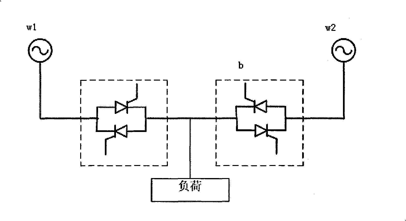
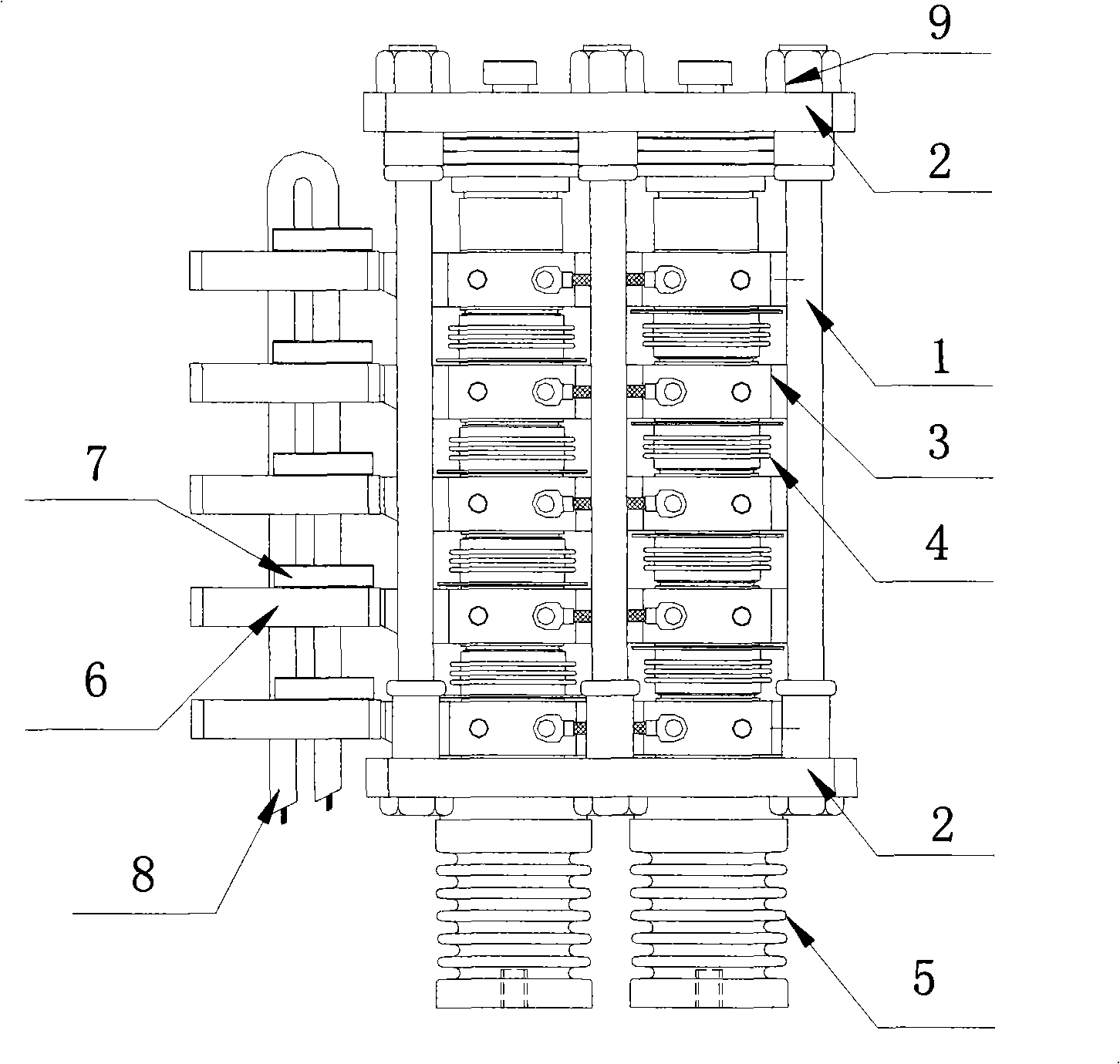
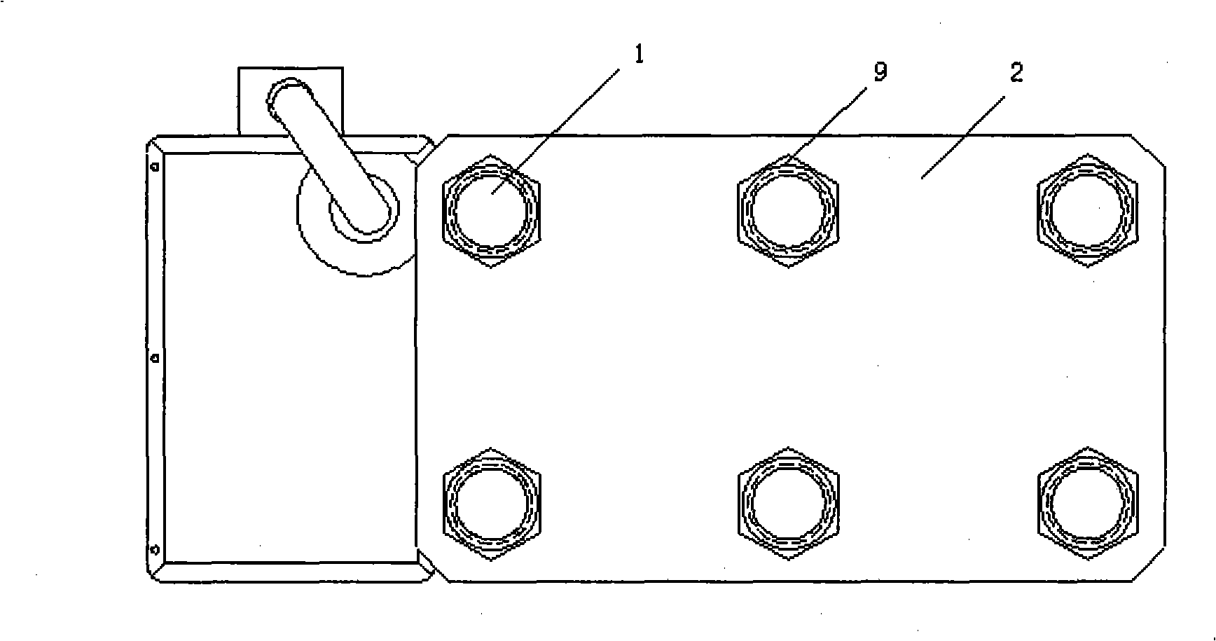
[0026] Such as figure 1 As shown, the solid-state transfer switch includes single-phase thyristor valve a and single-phase thyristor valve b, connected between the power supply w1 and the backup power supply w2, and the load is connected between the single-phase thyristor valve a and single-phase thyristor valve b. The working principle of the solid-state switch is that when the voltage fluctuation occurs in the power supply w1, the single-phase thyristor valve a is disconnected, the single-phase thyristor valve b is turned on, and the load is powered by the backup power supply w2. The present invention forms a thyristor valve unit by combining two forward and reverse thyristors connected in parallel, and a plurality of thyristor valve units are stacked vertically to form a thyristor valve string. Two sets of thyristor valve ...


PUM


Abstract

The invention relates to a high-power self-cooled thyristor valve and a vehicle for assembling the same. The invention is characterized in that: a single-phase thyristor valve body comprises two thyristor valve string, and insulating tension rods, flanges, radiating fins, high-potential trigger plates, energy-taking magnetic rings, high-voltage energy-transmitting cables and a plurality of retaining nuts which are symmetrically distributed; every two thyristors are in positive and negative parallel connection with each other through flexible cables on the radiating fins to form a thyristor valve unit; a plurality of thyristor valve units form a thyristor valve string through parallel connection and upright stacking; radiating fins are pressed between each layer of thyristor valve units at intervals; the two thyristor valve strings form a single-phase thyristor valve through positive and negative parallel connection; both ends of the insulating tension rods are respectively fastened between an upper flange and a lower flange through the retaining nuts; the high-voltage energy-transmitting cables are connected to the inside of the thyristor valve body through the energy-taking magnetic rings of the high-potential trigger plates; the single-phase thyristor valve body inputs and outputs current through two moving contacts; the two moving contacts and the thyristor valve body are fixed together through copper bars which are fixed on the upper end and the lower end of the insulating tension rods through the flanges; and annealed copper sheets which are communicated with the radiating fins are arranged on the copper bars.

Description

technical field [0001] The invention relates to a solid-state switch in high-voltage power supply facilities, in particular to a high-power self-cooling thyristor valve in the solid-state switch and a vehicle for its installation. Background technique [0002] With the development of science and technology and the improvement of human's requirements for the quality of electricity, medium and high voltage high power power electronic equipment will be widely used. In the field of power electronic equipment, electrical components such as thyristors, insulated gate power transistors (IGBTs), and diodes mainly work in the switching state and perform periodic conversions in different dynamic and static processes. In each process of conversion, the switching element itself will generate power loss, so the heating phenomenon is serious. If the heat cannot be taken away by the heat dissipation system as soon as possible, the normal operation of the switching element will be affected....

Claims


Application Information

Patent Timeline
Patent Type & Authority Applications(China)
IPC IPC(8): H01L25/00H01L23/48H01L23/367H01L21/50H02M1/00H02H7/10
CPCH01L2924/0002
Inventor 李金元李志麒蓝元良荆平于坤山王松岑刘兵
Owner CHINA ELECTRIC POWER RES INST
Why Eureka
Try Eureka