Clamping device for a device for machining workpiece

A technology for processing workpieces and tools, which is applied in the direction of manufacturing tools, metal processing equipment, tool holder accessories, etc., and can solve the problem of insufficient support and maintenance

Inactive Publication Date: 2008-10-22
赫曼利昆
View PDF1 Cites 2 Cited by
  • Summary
  • Abstract
  • Description
  • Claims
  • Application Information

AI Technical Summary

Problems solved by technology

[0004] The disadvantage of this arrangement is that the support and r

Method used


Image

  • Clamping device for a device for machining workpiece
  • Clamping device for a device for machining workpiece
  • Clamping device for a device for machining workpiece

Examples


Embodiment Construction

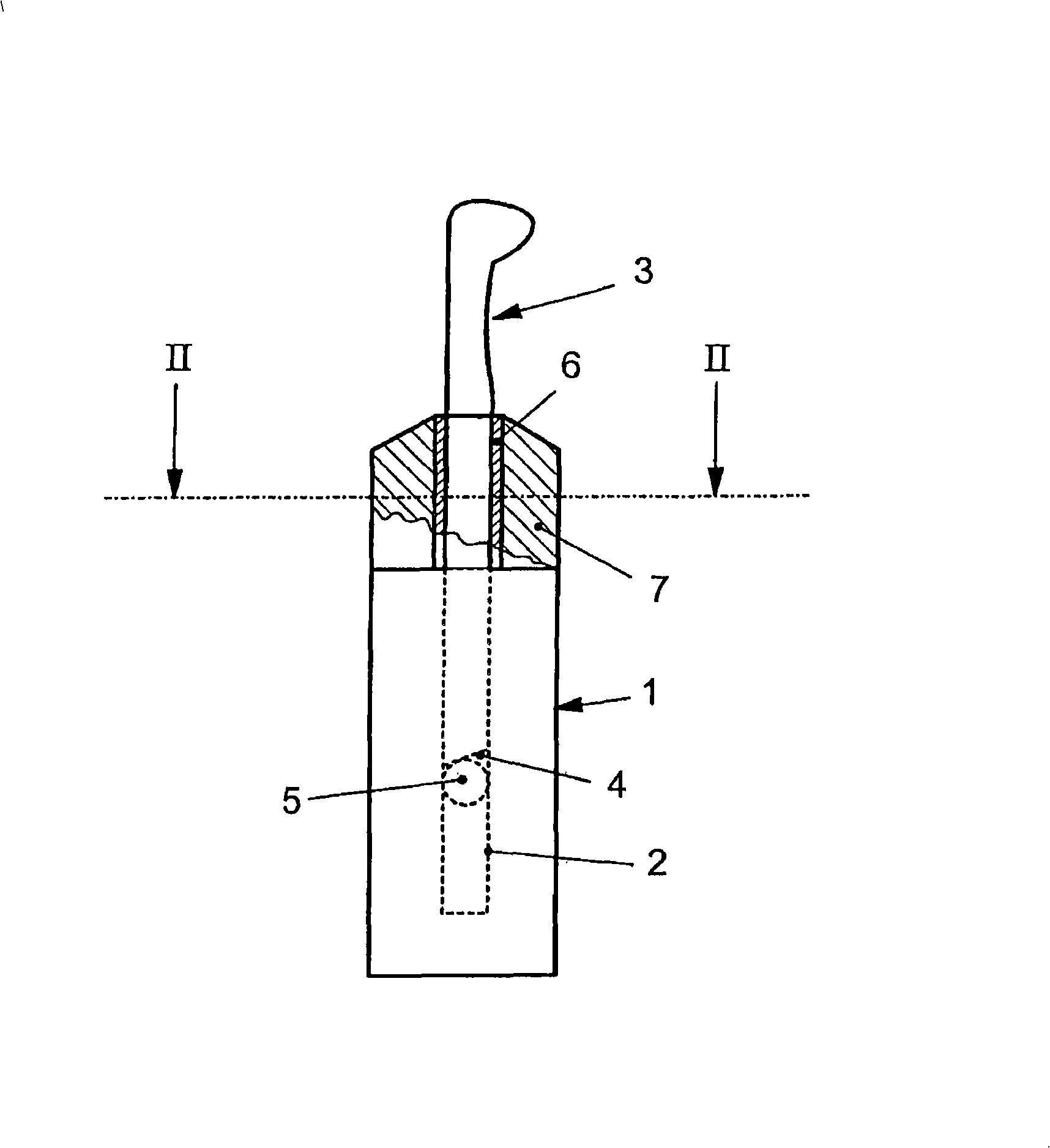
[0018] The device according to the invention for machining workpieces which are not shown in detail has a carrier 1 with a shaft bore 2 indicated by dashed lines. A tool 3 is inserted into the shaft hole 2 and has a bevel 4 at the end of the tool 3 in the shaft hole 2 . Said ramp 4 interacts with a rotation protection mechanism, here a cross-section pin 5 , as described in detail in DE 198 00 424 A1.

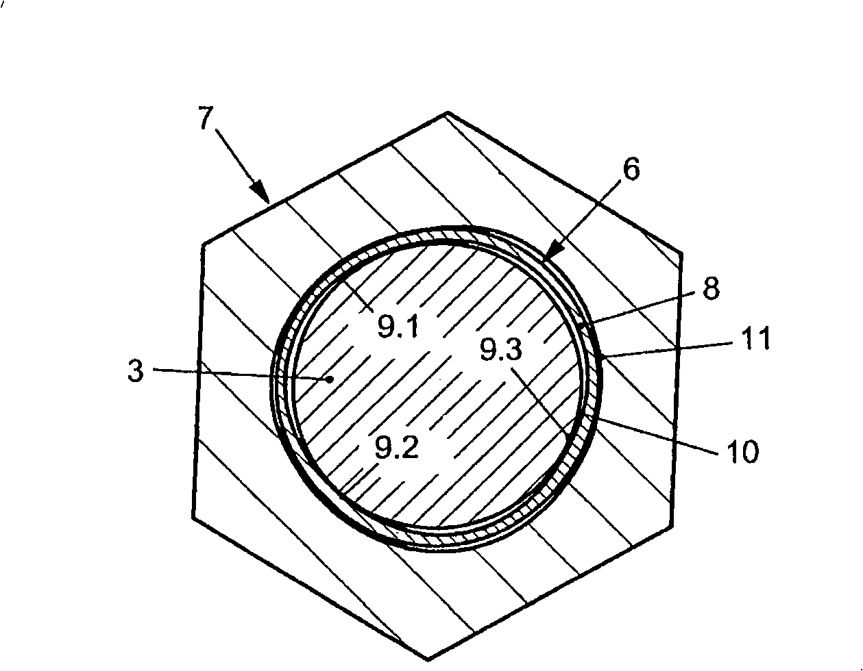
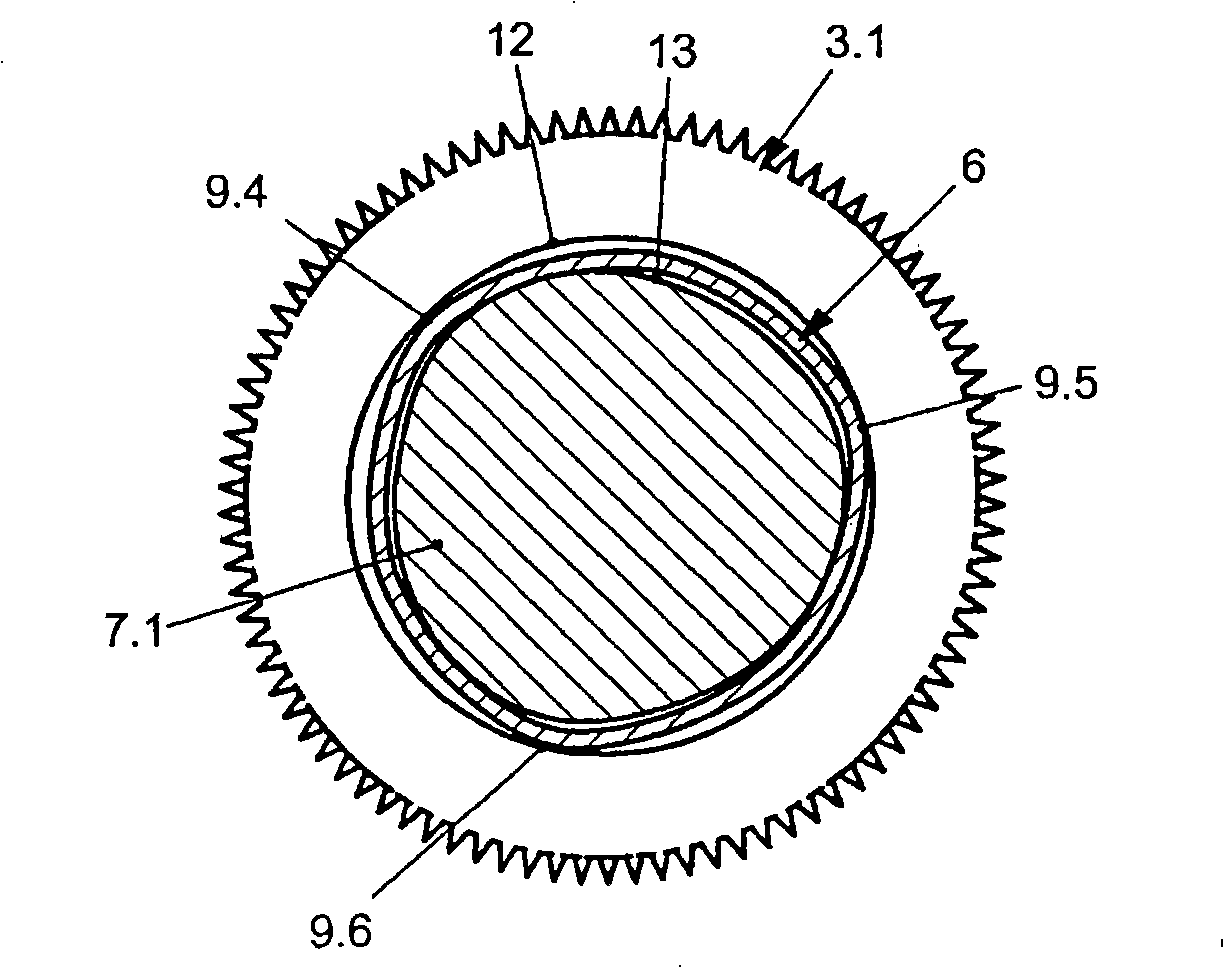
[0019] Before the tool 3 enters the shaft hole 2 it passes through a sleeve 6 surrounded by a rotating element 7 . Such as figure 2 As shown, the rotating element 7 is designed to be hexagonal.

[0020] According to the present invention and as figure 2 As shown in , the sleeve 6 has a non-circular design of the cover 8 . In the present embodiment, it is in contact with the cylindrical tool 3 at three locations 9.1, 9.2 and 9.3, while its inner face 10 has a very small section of rising or falling with the tool 3 in the region between them. Spacing (eg 3 / 100mm).

[0021]...


PUM


Abstract

The invention relates to a device for machining workpieces, comprising a tool (3, 3.1) that is connected to a support (1) via a clamping device. The invention is characterized in that the support (1) is associated with an out-of-round, deformable cylinder (6) which receives the tool or which engages in a recess (12) in the tool (3.1).

Description

technical field [0001] The invention relates to a device for machining workpieces with a tool connected to a support via a clamp. Background technique [0002] Such devices are well known and available in various shapes and forms on the market. They primarily function to machine workpieces in machining stations, for example in lathes, milling machines or the like. [0003] DE19800424A1 discloses a similar device in which a tool with a rod is inserted into a hole in the holder and held by a clamp. The tool tip face sits in the angled bore and interacts with the cross-section baffle. The cross-sectional baffle penetrates radially through a hole in the holder, and a tool is inserted into the hole and held in axial and radial position by axially acting clamps. [0004] A disadvantage of this arrangement is that the support of the tool is generally not sufficient in its radial position. Contents of the invention [0005] The object of the invention is to improve the radial ...

Claims


Application Information

Patent Timeline
IPC IPC(8): B23B31/117
CPCB23B31/1177B23B2231/48
Inventor 赫曼·利昆
Owner 赫曼利昆
Why Eureka
Try Eureka