Spiral mold and pipeline composite equipment with spiral mold

A spiral flow channel and spiral technology, applied in the field of composite pipe manufacturing equipment, can solve problems such as difficulty in ensuring the uniformity of the composite layer wall thickness, and achieve the effect of avoiding radial offset and uniform distribution

Pending Publication Date: 2021-08-24
SICHUAN GOLDSTONE-ORIENT NEW MATERIAL TECH CO LTD
View PDF0 Cites 0 Cited by
  • Summary
  • Abstract
  • Description
  • Claims
  • Application Information

AI Technical Summary

Problems solved by technology

[0006] The purpose of the present invention is to overcome the problem that the spiral die existing in the prior art is difficult to ensure the uniformity of the wall thickness of the composite layer, and to provide a spiral die that can effectively reduce the impact of the pressure on the feed end on the wall thickness of the extruded composite layer. uniformity effect

Method used


Image

  • Spiral mold and pipeline composite equipment with spiral mold
  • Spiral mold and pipeline composite equipment with spiral mold
  • Spiral mold and pipeline composite equipment with spiral mold

Examples


Embodiment Construction

[0033] Specific embodiments of the present invention will be described in detail below in conjunction with the accompanying drawings. It should be understood that the specific embodiments described here are only used to illustrate and explain the present invention, and are not intended to limit the present invention.

[0034] In the present invention, in the case of no contrary description, the used orientation words such as "up, down, left and right" usually refer to the up, down, left and right shown in the accompanying drawings; "inside and outside" Refers to the inside and outside of the outline of each part itself.

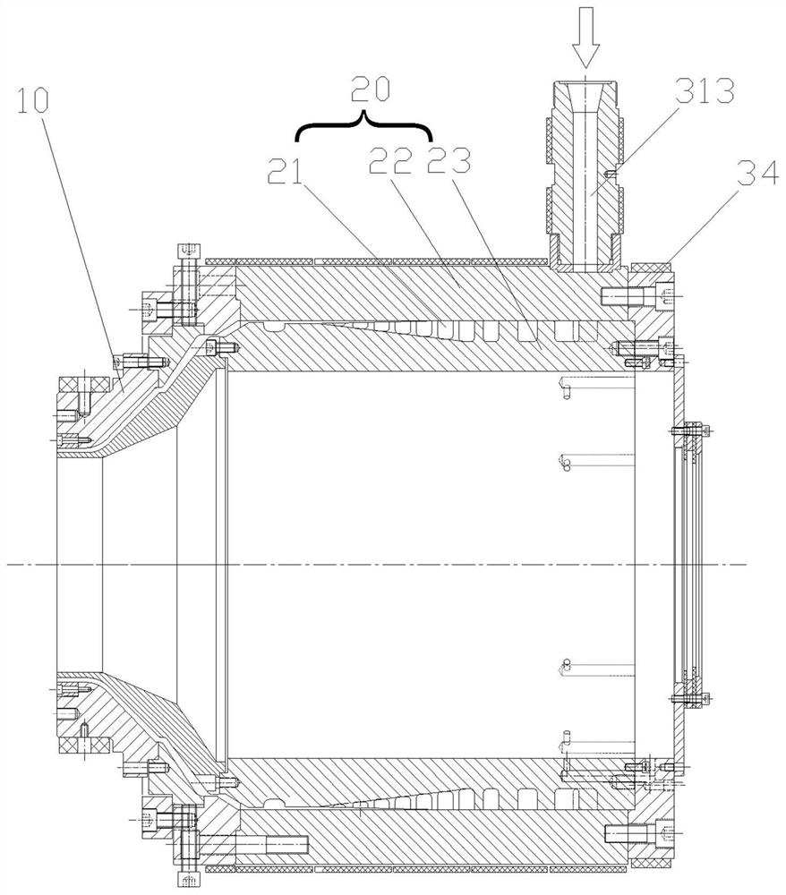
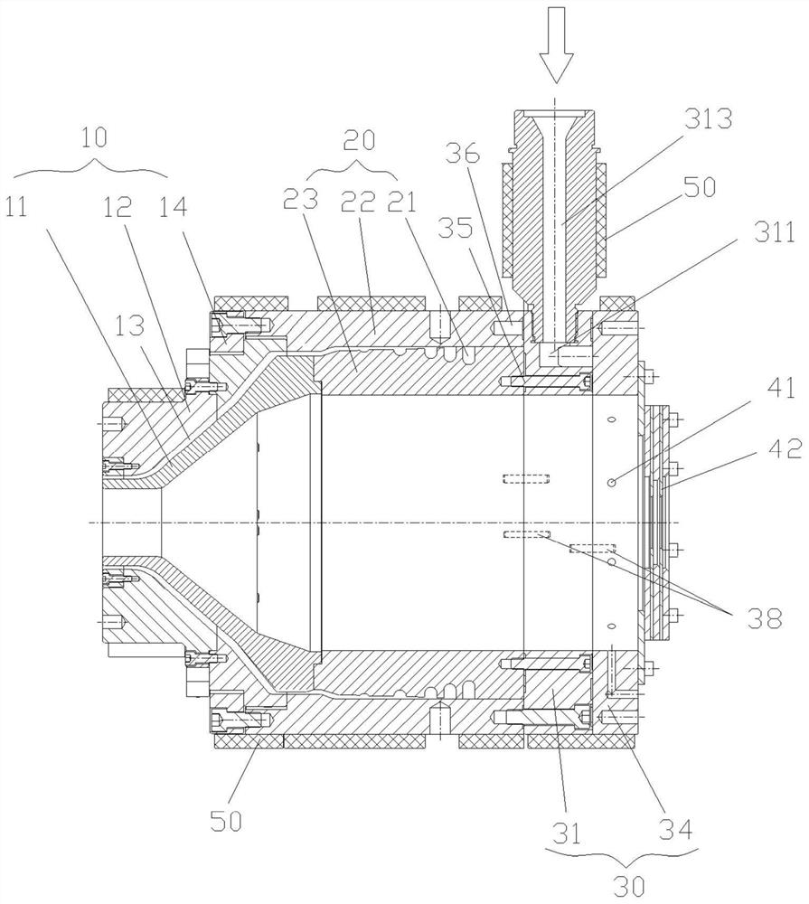
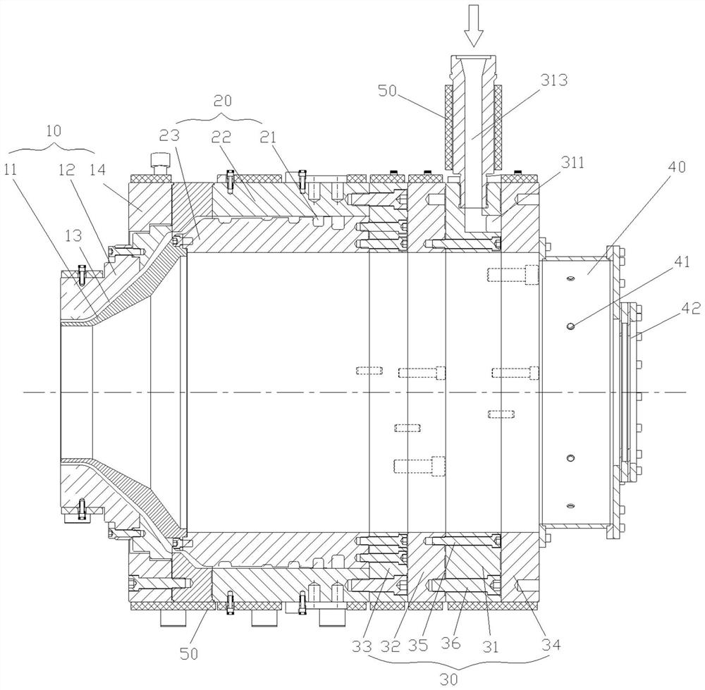
[0035] refer to Figure 2 to Figure 6 As shown, the first aspect of the present invention provides a spiral mold, which includes a spiral mold assembly 20 and a flow distribution assembly 30, and a plurality of spiral flow channels 21 extending spirally are formed in the spiral mold assembly 20; The splitter assembly 30 is arranged at the feed end of the sc...


PUM


Abstract

The invention relates to the field of composite pipeline manufacturing equipment, and discloses a spiral mold and pipeline composite equipment with the spiral mold. The spiral mold comprises a spiral mold assembly (20) provided with a plurality of spiral flow channels (21) and a flow dividing assembly (30) at least comprising a first flow dividing ring (31), the flow dividing assembly (30) is arranged at the feeding end of the spiral mold assembly (20), the first flow dividing ring (31) is provided with a first arc-shaped flow channel (311) extending in the circumferential direction and first material passing holes (312) penetrating and extending from the two ends of the first arc-shaped flow channel (311) in the axial direction, and the first flow dividing ring (31) can divide and convey material flow to the multiple corresponding spiral flow channels (21) through the first material passing holes (312). According to the spiral mold, feeding pressure can be converted into axial pressure when the material flow enters the spiral mold assembly, meanwhile, uniform distribution of composite materials in the circumferential direction is achieved, radial deviation of the spiral flow channels can be effectively avoided, and a composite layer with the uniform wall thickness is extruded.

Description

technical field [0001] The invention relates to composite pipeline manufacturing equipment, in particular to a spiral mold. On this basis, the present invention also relates to a pipe compounding device with the screw mold. Background technique [0002] In the manufacture of composite pipes, it is usually necessary to compound molten plastic on the outer peripheral surface of the pipe through a plastic extrusion die to form a plastic outer layer. For example, in the manufacturing process of steel mesh reinforced composite plastic pipe, a spiral mold can be used to form a PE outer layer on the outer peripheral surface of the pipe to be composited. Among them, since the pipes to be compounded need to run forward along the central axis of the spiral mold during the compounding process, the composite material is usually fed in by side feeding. [0003] Such as figure 1 Shown is a schematic cross-sectional structure diagram of a typical spiral mold, wherein molten plastic can ...

Claims


Application Information

Patent Timeline
Patent Type & Authority Applications(China)
IPC IPC(8): B29C48/32B29C48/70B29C48/76B29C48/151B29C48/86
CPCB29C48/146B29C48/151B29C48/32B29C48/705B29C48/76B29C48/865
Inventor 蒯一希付林
Owner SICHUAN GOLDSTONE-ORIENT NEW MATERIAL TECH CO LTD
Why Eureka
Try Eureka