Motor with small air gap, machining and assembling method of motorand electric tool

A small air gap, integrated technology, applied in the direction of electromechanical devices, electric components, manufacturing motor generators, etc., can solve the problems of difficult to meet the demand, poor concentricity between the stator and the rotor, etc., to improve the efficiency of the motor, small air gap, guarantee The effect of concentricity

Pending Publication Date: 2021-09-07
ZHEJIANG YAT ELECTRICAL APPLIANCE CO LTD
View PDF9 Cites 0 Cited by
  • Summary
  • Abstract
  • Description
  • Claims
  • Application Information

AI Technical Summary

Problems solved by technology

[0005] The purpose of the present invention is to provide a motor with a small air gap, a processing and assembling method, and an electric tool, which can effectively solve the problem in the prior art that it is difficult to obtain a small air gap that meets the demand due to poor concentricity between the stator and the rotor during the assembly process. Effectively improve motor efficiency

Method used


Image

  • Motor with small air gap, machining and assembling method of motorand electric tool
  • Motor with small air gap, machining and assembling method of motorand electric tool
  • Motor with small air gap, machining and assembling method of motorand electric tool

Examples


Embodiment 1

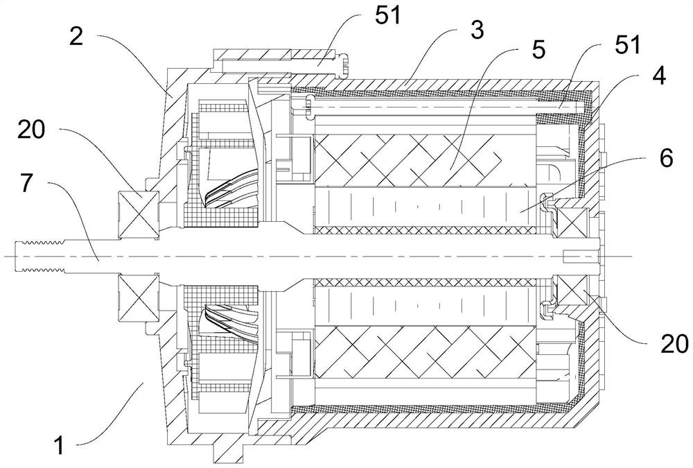
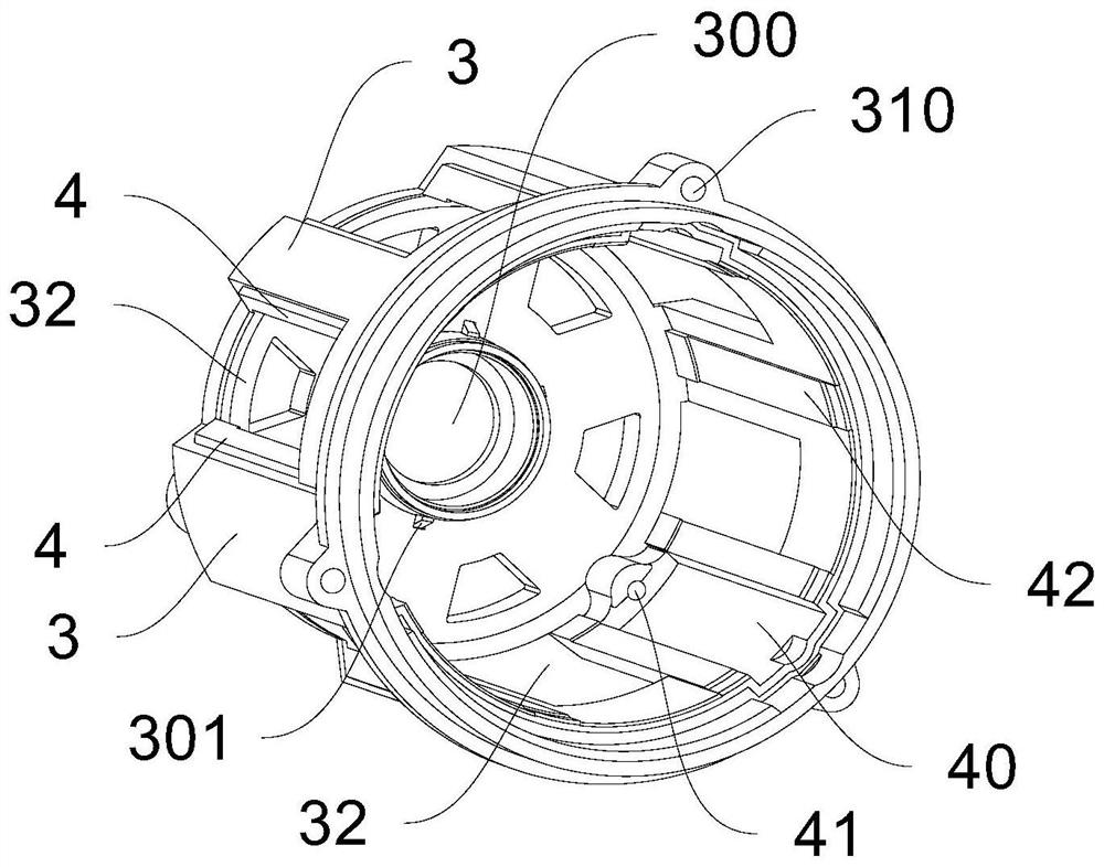
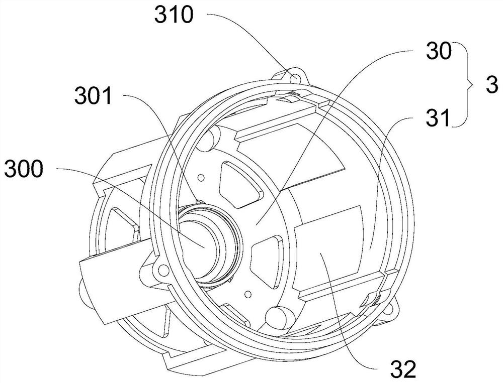
[0038] Embodiment one: if figure 1 , figure 2 , image 3 with Figure 4 As shown, a motor with a small air gap includes a front end cover 2, a casing 3, a stator 5, a rotor 6, a motor shaft 7 and a plastic insulating layer 4, wherein the casing 3 includes a rear end cover 30 and an annular shell 31, and the rotor 6 is fixed Connected on the motor shaft 7, the center of the front end cover 2 and the center of the rear end cover 30 are provided with a bearing chamber 300, and the two ends of the motor shaft 7 are respectively rotated and connected to the bearing 20 provided in the bearing chamber 300, and the front end cover 2 and the rear end cover 30 are fixedly connected with the stator 5 , the plastic insulating layer 4 is arranged outside the stator 5 to play an insulating role, and an air gap is formed between the stator 5 and the rotor 6 . The housing 3 in this embodiment forms an accommodating cavity for accommodating the stator 5, that is, the accommodating cavity i...

Embodiment 2

[0048] Embodiment 2: This embodiment provides a method for processing and assembling a motor with a small air gap, including the following steps, wherein the structure of the motor can be referred to Figure 1 to Figure 6 :

[0049] S10: The housing 3 of the motor is made by die-casting technology. The housing 3 includes a rear end cover 30 and an annular shell 31. The rear end cover 30 of the housing 3 includes a bearing chamber 300 for installing the motor shaft 7. The annular shell 31 of the housing 3 includes The first mating end surface used to closely fit with the front end cover 2;

[0050] S20: putting the shell 3 as an insert into the injection cavity of the injection mold;

[0051] S30: filling the injection molding cavity with molten plastic, and injecting the inner surface of the shell 3 to form a plastic insulating layer 4;

[0052] S40: Manufacture the front end cover 2 of the motor. The front end cover 2 includes a second matching end surface for closely fitti...

Embodiment 3

[0056] Embodiment three: as Figure 7 As shown, this embodiment provides an electric grinding tool, including a casing 8, a working head 82, a controller 81 and a motor 1, wherein the rear end of the casing 8 is provided with a gripping portion 80 for the operator to grasp, A motor 1 is installed in the casing 8 , the output shaft of the motor 1 is connected with the working head 82 for driving the working head 82 to work, and the controller 81 is connected with the motor 1 for controlling the start and stop of the motor 1 . Wherein, the motor 1 installed in the tool is a motor with a small air gap provided in the first embodiment. Since the tool is equipped with the above-mentioned motor with a small air gap, the electric tool has the advantages of long service life and high reliability of the whole machine, and at the same time reduces the cost. It can be understood that the motor is not limited to be applied to the electric grinding tool provided in this embodiment, and ca...


PUM


Abstract

The invention discloses a motor with a small air gap. The motor comprises a stator and a plastic insulating layer, the plastic insulating layer is arranged outside the stator, the motor also comprises a shell, the shell comprises a rear end cover and an annular shell, the shell forms an accommodating cavity for accommodating the stator, the plastic insulating layer is integrally formed in the accommodating cavity through injection molding, and the plastic insulating layer and the shell are integrated through injection molding. The invention further discloses an electric tool based on the motor. The invention further discloses a machining and assembling method of the motor with the small air gap. According to the invention, the stator has high concentricity relative to the rear end cover in the assembling process, so that a required small air gap can be obtained between the stator and the rotor, and the efficiency of the motor is effectively improved.

Description

technical field [0001] The invention belongs to the field of motor equipment, and in particular relates to a motor with a small air gap, a processing and assembling method thereof, and an electric tool. Background technique [0002] Brushless switched reluctance motor is a new type of speed control motor, which is the latest generation of speed control system following frequency conversion speed control system and brushless DC motor speed control system. It has a simple and firm structure, wide speed range and high system reliability. Compared with the commonly used high-voltage brushless motors, the cost can be greatly reduced because the rotor does not need windings and permanent magnets. Applying it to electric tools can make electric tools have the advantages of long service life and high reliability . However, due to the small size of electric tools, the efficiency of the motor (the ratio of output power to input power, usually expressed as a percentage) is relatively ...

Claims


Application Information

Patent Timeline
Patent Type & Authority Applications(China)
IPC IPC(8): H02K5/08H02K15/14
CPCH02K5/08H02K15/14
Inventor 刘兵建游瑞华程恩仿
Owner ZHEJIANG YAT ELECTRICAL APPLIANCE CO LTD
Why Eureka
Try Eureka