
Self-positioning permanent internal mold for cast-in-situ reinforced concrete structure and construction method thereof

A reinforced concrete and self-positioning technology, which is applied to building components, building structures, floor slabs, etc., can solve problems such as increased construction costs and complicated construction measures, and achieve the effects of improving construction efficiency, realizing engineering design intentions, and reducing construction costs

Inactive Publication Date: 2008-10-29
宫海西
View PDF0 Cites 9 Cited by
  • Summary
  • Abstract
  • Description
  • Claims
  • Application Information

AI Technical Summary

Problems solved by technology

[0006] In order to overcome the shortcomings of the above-mentioned internal mold products, the task of the present invention is to provide an improved self-positioning permanent internal mold for cast-in-place reinforced concrete structures and its construction method, which solves the construction measures existing in the existing internal mold products Complexity, increased construction costs, and problems that are prone to engineering hidden dangers

Method used


Image

  • Self-positioning permanent internal mold for cast-in-situ reinforced concrete structure and construction method thereof
  • Self-positioning permanent internal mold for cast-in-situ reinforced concrete structure and construction method thereof
  • Self-positioning permanent internal mold for cast-in-situ reinforced concrete structure and construction method thereof

Examples


Embodiment Construction

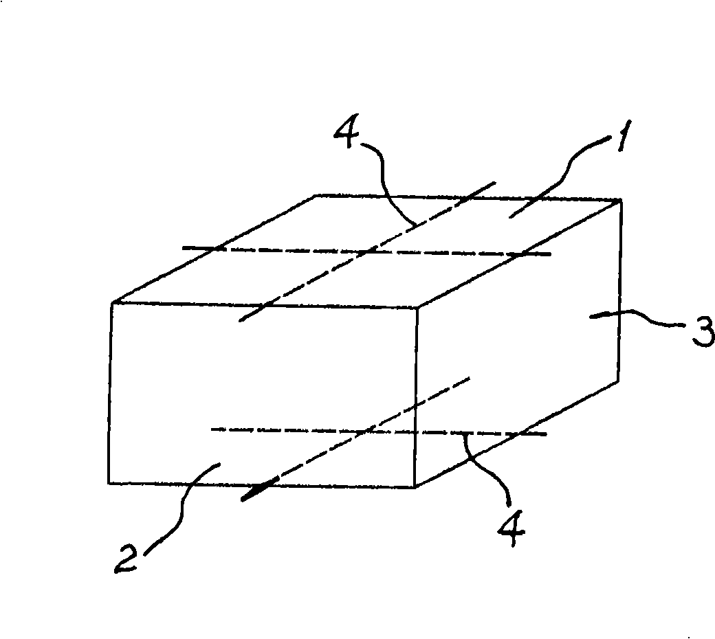
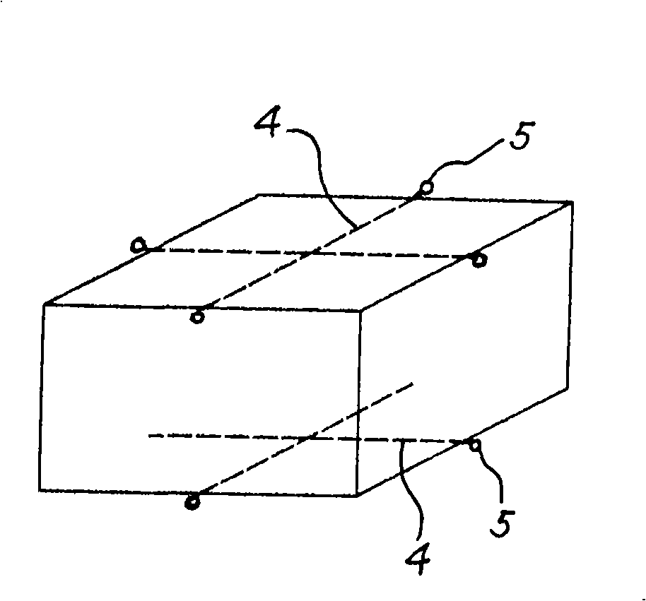
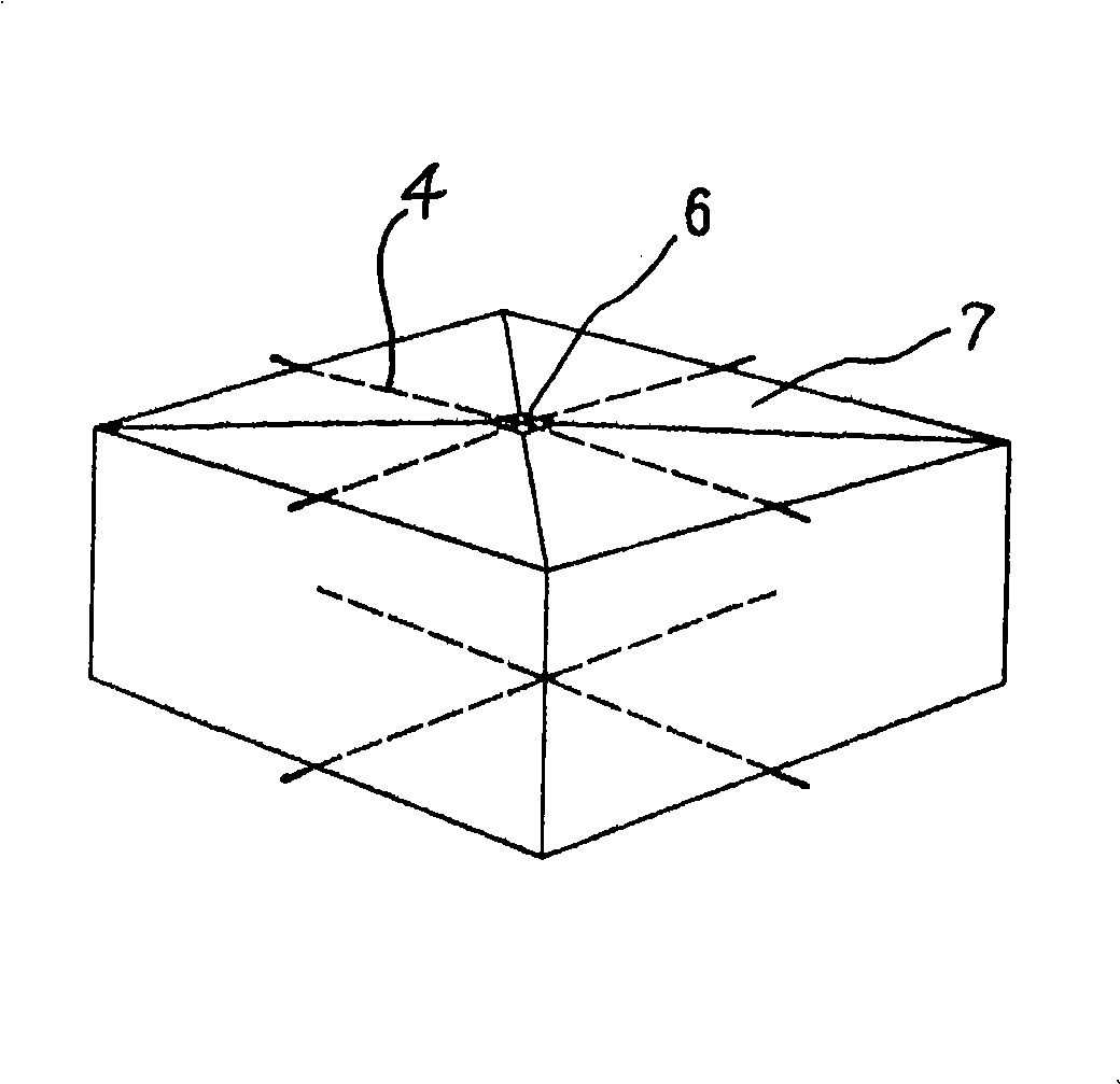
[0035] See Figure 1 to Figure 8 , The present invention is a self-positioning permanent internal mold for cast-in-situ reinforced concrete structures, which includes a top plate 1, a bottom plate 2 and four side walls 3. The top plate 1 and the bottom plate 2 are respectively pre-embedded with iron wires 4 for anti-floating and positioning, and the ends of each iron wire 4 protrude from the side wall 3 to connect and fix the top rib of the rib beam and the bottom rib of the rib beam.

[0036] Such as Figure 1 to Figure 4 As shown in the figure, the iron wires 4 are embedded in the top plate 1 and the bottom plate 2 in a cross shape, and the ends of each iron wire 4 protrude at the junction of the top plate 1 and the side wall 3 and the junction of the bottom plate 2 and the side wall 3, forming X-shaped spaces that are parallel and perpendicular to each other.

[0037] Another example Figure 5 to Figure 8 As shown in the figure, the iron wires 4 are linearly embedded on the top ...


PUM


Abstract

The invention relates to a self-positioning permanent internal mold used for a cast-in-situ reinforced concrete structure, which comprises a top plate, a soleplate and four sidewalls. Iron wires used for float resistance and positioning are embedded in the top plate and the soleplate respectively. The ends of the iron wires protrude beyond the sidewalls. According to the construction method of the invention, bottom stiffeners of a floor slab and steel bars of a ribbon strip are tied up firstly; a ribbed slab is directly tied up with the steel bars of the ribbon strip; pipelines are embedded; ribbon strip bottom stiffeners are fixed to a molding board with iron wires to resist the buoyancy on the overall internal mold; an internal mold cushion block is installed; the internal mold is lifted; the internal mold is installed; the upper steel bars of the floor slab are tied up; construction access roads are established with the molding board, and concrete pump pipes are erected; concrete is cast and vibrated. As through iron wires and sectional iron wires are embedded in the top plate and the soleplate, the bearing strength of the internal mold is improved, thus facilitating construction and reducing the failure rate. The internal mold has low cost, high cost performance, and high operability. By adopting the internal mold and the application method of the internal mold, the construction cost is reduced, the operating efficiency is improved, and the construction quality is ensured.

Description

Technical field [0001] The invention relates to building materials, in particular to a self-positioning permanent internal mold for cast-in-place reinforced concrete structures and a construction method thereof. Background technique [0002] The existing disposable inner molds for cast-in-situ concrete hollow and multi-ribbed floor structures are separated from the inner mold products for positioning, anti-floating measures and accessories. The hollow and solid inner molds objectively have buoyancy and Squeeze force. The existing anti-floating supporting measures for internal mold products are positioning steel bars at the upper or lower part, positioning steel bars and rib beam bottom reinforcements are connected with iron wires, and the rib beam bottom reinforcements are self-fixed with iron wires through the floor construction template or fixed with the lower scaffolding. The positioning steel bars increase the amount of floor steel bars, the positioning and anti-floating meas...

Claims


Application Information

Patent Timeline
IPC IPC(8): E04B5/36E04B5/18
Inventor 宫海西
Owner 宫海西
Learn More