Vertical axis aerogenerator with magnetic suspension for reducing gravity force and frictional force

A technology for wind turbines and generators, which is applied in the directions of holding devices, engine components, and shafts using magnetic attraction or thrust, can solve the problems of troublesome, cumbersome, complicated structure of magnetic suspension bearings, and achieves compact structure and simple overall structure. , avoid the effect of contact

Inactive Publication Date: 2010-07-14
林修鹏
View PDF7 Cites 0 Cited by
  • Summary
  • Abstract
  • Description
  • Claims
  • Application Information

AI Technical Summary

Problems solved by technology

[0002] Magnetic levitation bearings are applied to vertical axis wind turbines, which reduce or basically eliminate the radial friction force generated by ball bearings for the drive shaft and the axial friction force generated by heavy wind wheels and drive shafts, but the existing magnetic levitation vertical axis In wind power generators, the magnetic suspension bearings bearing axial force are troublesome to install, and the structure is complex and cumbersome. The Chinese invention patent, patent number 200610122794.4 "Vertical Full Magnetic Suspension Wind Power Generator" discloses the magnetic suspension bearing technology bearing axial force: generator The rotor is installed on the drive shaft, and the drive shaft is vertically installed on the magnetic levitation loading platform composed of the casing, suspension block, permanent magnet and adjustment block. While eliminating the frictional force generated by the axial force, there are problems such as troublesome installation of magnetic suspension bearings, complex structure and cumbersome problems

Method used


Image

  • Vertical axis aerogenerator with magnetic suspension for reducing gravity force and frictional force
  • Vertical axis aerogenerator with magnetic suspension for reducing gravity force and frictional force
  • Vertical axis aerogenerator with magnetic suspension for reducing gravity force and frictional force

Examples


Embodiment Construction

[0018] Description with reference to the accompanying drawings.

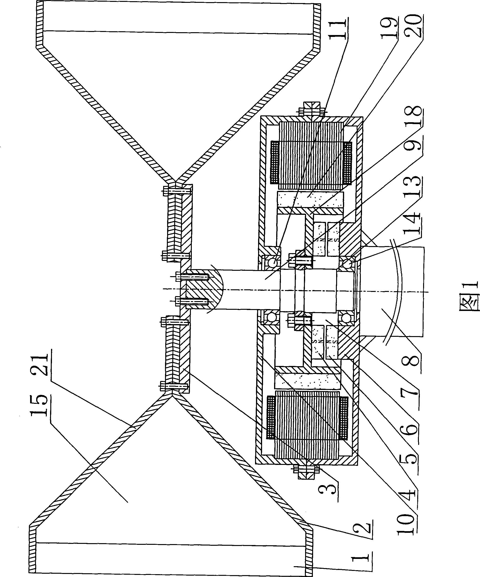
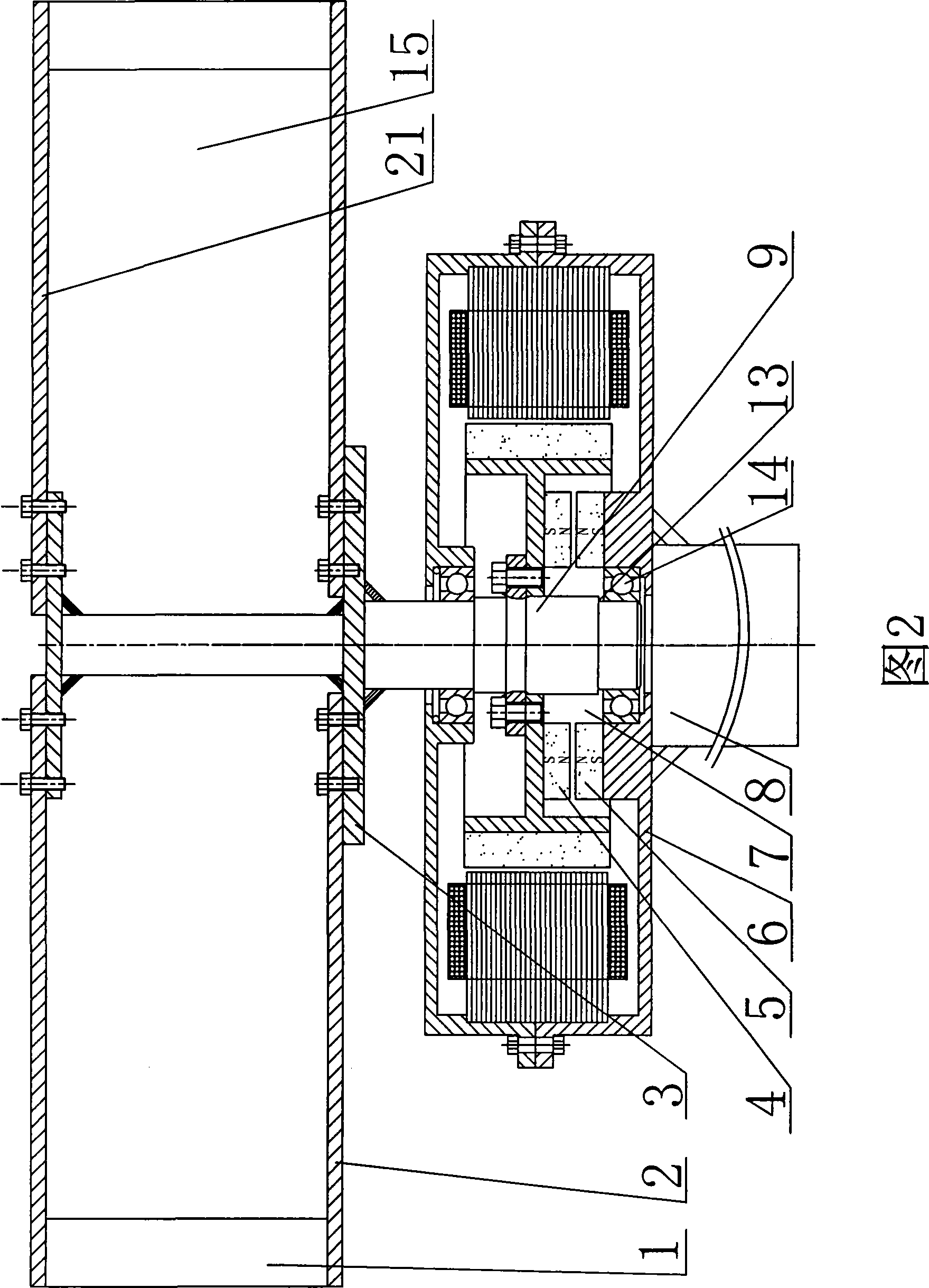
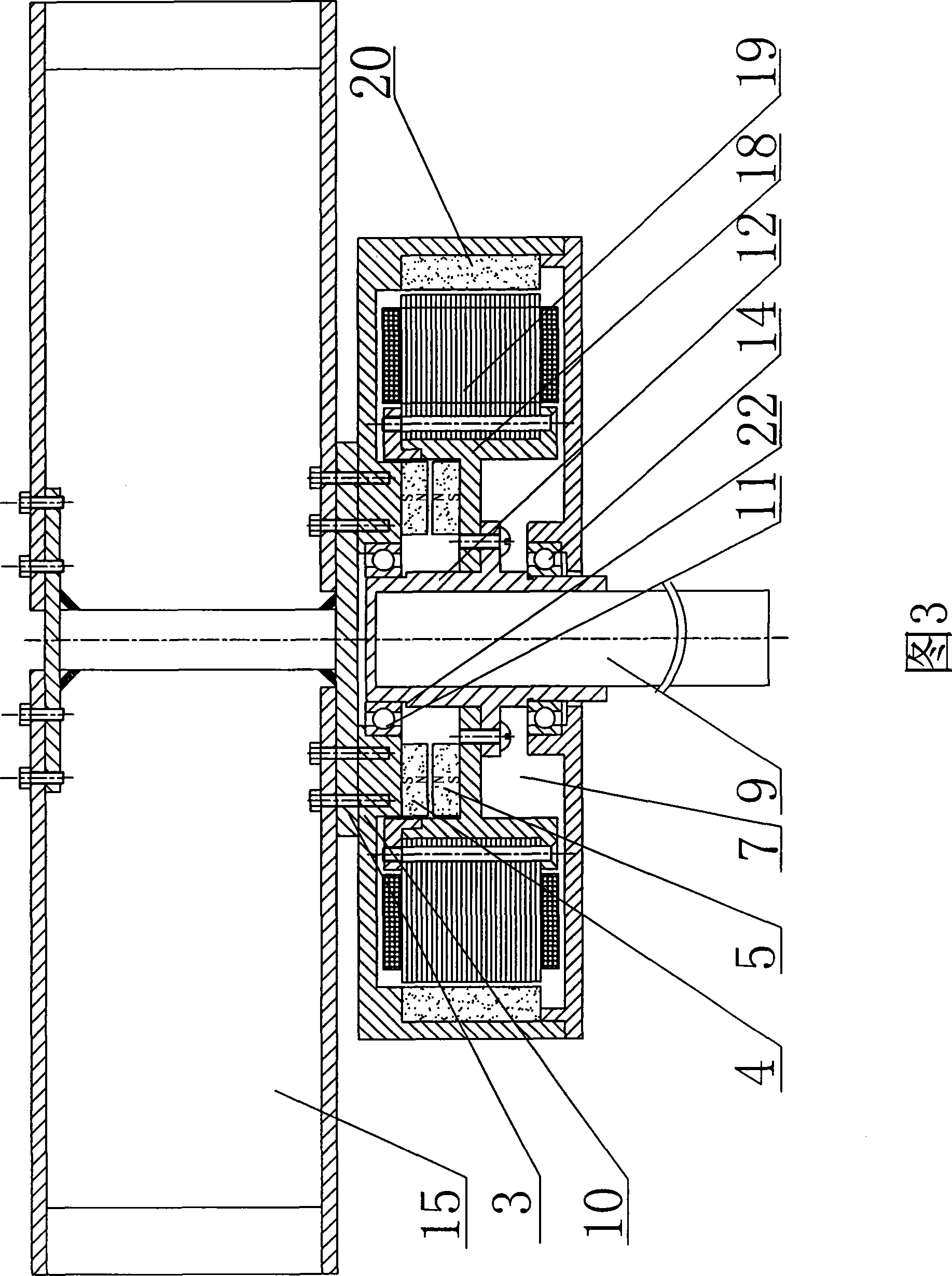
[0019] figure 1 Shown is an H-shaped wind wheel and an inner rotor generator. At this time, the generator shaft 9 is the rotor, and the upper end cover 10 and the lower end cover 6 of the generator are the stator. The upper and lower ends of the blade 1 of the wind wheel 15 are connected to one end of the upper arm 21 and the lower arm 2 respectively, and the other ends of the upper arm 21 and the lower arm 2 are connected together and connected to the lower flange 3 of the wind wheel 15, the lower flange The disc 3 is fixedly connected to the generator shaft 9 of the generator 7, the bracket disc 18 is fixedly connected to the collar of the generator shaft 9, the rotor magnetic pole 20 is fixed on the outer edge of the bracket disc 18, and the rotor permanent magnet 4 is fixed on the bracket On the frame plate 18, between the rotor magnetic pole 20 and the generator shaft 9, the stator permanent magnet 5 is fi...


PUM


Abstract

The invention relates to a wind power generator of a vertical shaft with gravity and friction reduced by magnetic suspension, which comprises a wind wheel, a generator with a stator, a rotor and a generator shaft, wherein, the permanent stator magnet and the permanent rotor magnet of a magnetic suspension bearing are respectively fixed on the stator and the rotor and arranged top down with the permanent stator magnet under the permanent rotor magnet and the two opposite surfaces have the same polarity. The permanent stator magnet and the permanent rotor magnet of the magnetic suspension bearing are arranged inside the generator with compact structure. The wind power generator has simple integral structure and convenient site installation. The clearance of the upwards running and the downwards running of the generator shaft is less than that of the two opposite surfaces of the permanent stator magnet and the permanent rotor magnet, thus avoiding the contact of the permanent stator magnet and the permanent rotor magnet and protecting the permanent stator magnet and the permanent rotor magnet automatically. After the disappearance of special external force, the generator shaft resetsautomatically.

Description

technical field [0001] The invention belongs to the field of generators, in particular to a vertical axis wind power generator with magnetic suspension and gravity reduction friction force. Background technique [0002] Magnetic levitation bearings are applied to vertical axis wind turbines, which reduce or basically eliminate the radial friction force generated by ball bearings for the drive shaft and the axial friction force generated by heavy wind wheels and drive shafts, but the existing magnetic levitation vertical axis In wind power generators, the magnetic suspension bearings bearing axial force are troublesome to install, and the structure is complex and cumbersome. The Chinese invention patent, patent number 200610122794.4 "Vertical Full Magnetic Suspension Wind Power Generator" discloses the magnetic suspension bearing technology bearing axial force: generator The rotor is installed on the drive shaft, and the drive shaft is vertically installed on the magnetic lev...

Claims


Application Information

Patent Timeline
Patent Type & Authority Patents(China)
IPC IPC(8): F16C32/04H02K7/09H02N15/00F16C39/06
CPCF16C39/066F16C2360/31
Inventor 林修鹏
Owner 林修鹏
Why Eureka
Try Eureka