
Frequency-flashing light source control device

A light source control and stroboscopic technology, which is applied in the field of stroboscopic light source control devices, can solve problems such as light pollution, too bright image quality, poor imaging quality, etc., and achieve the effect of shooting

Active Publication Date: 2008-10-29
SHANGHAI BAOKANG ELECTRONICS CONTROL ENG
View PDF0 Cites 20 Cited by
  • Summary
  • Abstract
  • Description
  • Claims
  • Application Information

AI Technical Summary

Problems solved by technology

[0003] 1. Use the exposure compensation method to increase the exposure, but this will cause the overall image quality to be too bright;
[0004] 2. Using the currently popular ultra-wide dynamic CMOS sensor, its essence is to use different exposures for different areas to satisfy the imaging of the background and key objects at the same time. This technology can better solve the imaging of still objects, but if the key If the object is in a fast-moving state, the image quality will be poor;
[0005] 3. Use supplementary lighting methods, such as flashlights and permanent lights, but in order to provide sufficient illumination, the above light sources will cause a certain degree of light pollution. must use a lot of power

Method used


Image

  • Frequency-flashing light source control device

Examples


Embodiment Construction

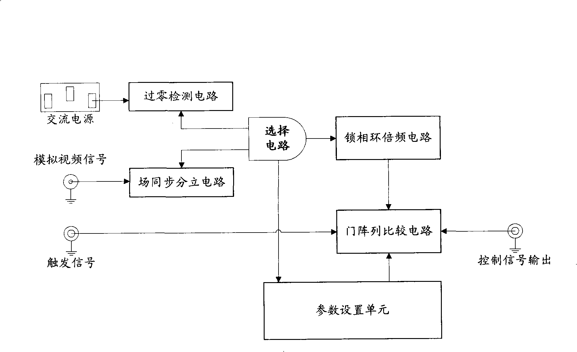
[0016] Such as figure 1 As shown, it includes a zero-crossing detection circuit for collecting power frequency signals, a field synchronization discrete circuit for collecting frequency signals in analog video signals, and a synchronization signal for selecting between the zero-crossing detection circuit and the field synchronization separation circuit. A selection circuit, a phase-locked loop frequency multiplier circuit, a gate array comparison circuit and a parameter setting unit.

[0017] The zero-crossing detection circuit provides a 50Hz reference signal of power synchronization mode by detecting the zero-crossing signal of the AC220V AC power supply; the field synchronization discrete circuit separates the 50Hz reference signal of video synchronization from the input analog video signal, and the field synchronization Discrete circuits can be implemented by video sync signal separation chips.

[0018] The selection circuit selects the reference signal according to the p...


PUM


Abstract

The invention relates to a light management device in a monitoring system, in particular to a stroboscopic light management device which comprises a synchronous signal unit, a frequency multiplication unit and a trigger control unit, wherein, the frequency multiplication unit receives a standard reference signal sent from the synchronous signal unit and outputs a frequency multiplication signal. When receiving a trigger signal, the trigger control unit outputs a control signal with a given pulse width according to the obtained frequency multiplication signal. By adopting a synchronization technique, the device of the invention ensures stroboscopic lights emitted by a light source and a shutter of a camera to be synchronous, so that all luminous power is exerted during the action period of the shutter of the camera, while during the period of closing the shutter of the camera, no lights is emitted or the lowest brightness is kept. In addition, frequency of a strobe is increased to 100Hz, therefore, no influence is imposed on human eyes, and the illumination intensity of backlighting parts does not need to be considered when the camera shoots backlighting pictures. The light supplementation of the backlighting parts is realized by an impulse LED lamp and the shooting of backlighting objects moving at high speed can be realized.

Description

technical field [0001] The invention relates to a light source control device in a monitoring system, in particular to a frequency light source control device. Background technique [0002] When shooting scenes with typical backlight characteristics (such as the entrance and exit of the building hall), the existing monitoring system adopts different solutions to solve the problem that the background light is too bright and the key objects are dim, but each method also has different effects. There are different problems, typical methods such as: [0003] 1. Use the exposure compensation method to increase the exposure, but this will cause the overall image quality to be too bright; [0004] 2. Using the currently popular ultra-wide dynamic CMOS sensor, its essence is to use different exposures for different areas to satisfy the imaging of the background and key objects at the same time. This technology can better solve the imaging of still objects, but if the key If the obj...

Claims


Application Information

Patent Timeline
Patent Type & Authority Applications(China)
IPC IPC(8): H05B37/02F21S10/06F21V23/00G03B15/02F21Y101/02F21Y115/10
Inventor 蒋松涛俞天涯
Owner SHANGHAI BAOKANG ELECTRONICS CONTROL ENG
Learn More