Directly-mounting type bar shape wiring block and slide tapping switch using the same

A tap changer, terminal board technology, applied in contact drive mechanism, transformer/inductor coil/winding/connection, transformer, etc., can solve problems such as bolt damage, pouring position, loosening, etc.

Active Publication Date: 2008-11-05
SHUANGCHENG ELECTROMECHANICAL TECH DEV
View PDF0 Cites 8 Cited by
  • Summary
  • Abstract
  • Description
  • Claims
  • Application Information

AI Technical Summary

Problems solved by technology

[0003] The purpose of the present invention is to provide a direct-mounted strip terminal board to overcome the defect that the existing transforme

Method used


Image

  • Directly-mounting type bar shape wiring block and slide tapping switch using the same
  • Directly-mounting type bar shape wiring block and slide tapping switch using the same
  • Directly-mounting type bar shape wiring block and slide tapping switch using the same

Examples


specific Embodiment approach 1

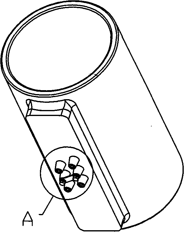
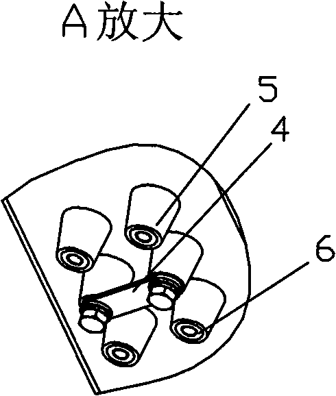
[0006] Specific implementation mode one: the following combination Figure 5 and Figure 6 This embodiment will be specifically described. The direct-mounted strip wiring board of this embodiment is composed of a strip-shaped substrate 11 of insulating material, three to ten conductive sheets 12 and three to ten sets of wiring assemblies, and all the wiring assemblies are evenly distributed along the length direction of the substrate 11. Each set of wiring components includes screws 13-1 and conductive posts 13-2. The conductive posts 13-2 penetrate the upper and lower surfaces of the substrate 11 and are integrally injection molded with the substrate 11. The lower ends of the conductive posts 13-2 are connected to the screws 13-2. 1. Rotate and fix one end of the conductive sheet 12 between the lower surface of the substrate 11 and the screw 13-1, and the polished rod end of the conductive post 13-2 hangs out of the upper surface of the substrate 11. Since the end of the co...

specific Embodiment approach 2

[0008] Specific implementation mode two: the following combination Figure 5 and Figure 6 This embodiment will be specifically described. The difference between this embodiment and the first embodiment is that: the upper surface of the substrate 11 is provided with a tapered sleeve 11-3 surrounding the conductive column 13-2, the material of the tapered sleeve 11-3 is the same as that of the substrate 11, and the tapered sleeve 11-3 It is integrally molded with the substrate 11 and the conductive pillar 13-2. Such an arrangement improves the connection strength between the substrate 11 and the conductive pillars 13-2. Other compositions and implementations are the same as the first implementation.

specific Embodiment approach 3

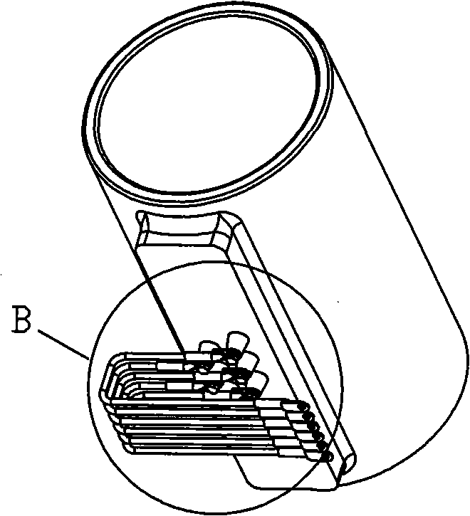
[0009] Specific implementation mode three: the following combination Figure 7 This embodiment will be specifically described. In this embodiment, the sliding tap changer using a direct-mounted strip terminal board is composed of a direct-mounted strip-shaped terminal board a, three to ten transformer terminal posts 5 and sliding contacts b, and all terminal posts 5 are distributed in On one side or both sides of the direct-installation strip terminal board a, the protruding end of the conductive piece 12 of the direct-installation strip terminal board a is fixed on the terminal post 5, and can slide through the direct-installation strip terminal board one by one. The length H of the conductive sheet of the sliding contact b on the outer cylindrical surface of the conductive posts 13 - 2 of the wiring board a is greater than the distance L between two adjacent conductive posts 13 - 2 and less than 2L.


PUM


Abstract

Provided is a direct type bar terminal assembly and a slide tap switch applying the same, relating to the terminal assembly of the dry type transformer primary coil tap, also relating to the slide tap switch applying the same, wherein the former overcomes the defect that the shifting causes the loose of the insert or the pouring position, and the latter solves the defect that cost is increased because of the addition of the cables. The former includes a bar base plate made of insulation materials, the conducting strips and the connection modules, wherein the connection modules are arranged in a row along the length direction of the base plate, including a screw and a conduction poles passing through the base plate, and the lower end is fixed with one end of the conduction piece combined with the screw. The latter includes a direct type bar terminal assembly, a wire holder of the transformer and a slider; the end of the conduction piece of the direct type bar terminal assembly is fixed on the wire holder, and the slider slides the external column surface of the direct type bar terminal assembly in turn.

Description

technical field [0001] The invention relates to a wiring board used for taps of the primary side coil of a dry-type transformer, and also relates to a sliding tap changer using the wiring board. Background technique [0002] Such as figure 1 and figure 2 As shown, several terminals 5 of the transformers arranged in two rows are respectively connected to the taps of the primary coil inside the transformer. By changing the wiring relationship between the terminals 5, the user can change the connection relationship between the taps of the primary coil of the transformer, so as to Change the output voltage of the transformer. Currently, a conductive connecting plate 4 is generally used to connect two terminal posts 5 . Fix the two ends of the conductive connection plate 4 to a terminal 5 respectively by bolt 1. When you want to change the terminal 5 to change the output gear of the transformer, you need to loosen the bolt 1, and then connect the ends of the conductive connec...

Claims


Application Information

Patent Timeline
IPC IPC(8): H01F29/04H01F27/29H01H3/32
Inventor 王继忠刘明
Owner SHUANGCHENG ELECTROMECHANICAL TECH DEV
Why Eureka
Try Eureka