Method for deicing aerial power line with load

A power line and ice melting technology, which is applied in the field of switching switches, can solve the problems of icing of overhead high-voltage transmission lines and a great threat to the safe and reliable operation of power systems.

Inactive Publication Date: 2008-11-05
华旭东
View PDF0 Cites 6 Cited by
  • Summary
  • Abstract
  • Description
  • Claims
  • Application Information

AI Technical Summary

Problems solved by technology

[0002] The ice melting of high-voltage transmission lines is generally carried out when the operation is stopped,...

Method used


Image

  • Method for deicing aerial power line with load
  • Method for deicing aerial power line with load
  • Method for deicing aerial power line with load

Examples


Embodiment Construction

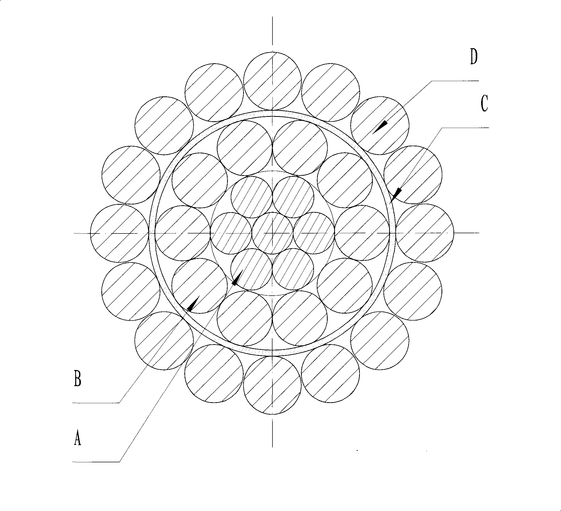
[0008] Refer to Figure 1 of the instruction manual. For power lines of this specification, the DC resistance at -5 degrees after A and B are connected in parallel is 0.1480Ω / KM, and the resistance after A, B, and D is connected in parallel is 0.0567Ω / KM. When D passes through 200A current in parallel, the line loss is 2268W / KM. When A and B are connected in parallel, they pass through 200A current. The surface temperature of the wire is higher than zero. If the ice-melting effect is not good, the current passing through the wire can be appropriately increased. When the current is 200A, the voltage drop at both ends of the wire is 30V / KM, so that the ice-melting switch can be installed every 75KM.


PUM


Abstract

Provided is a method which can change the carrying current section of the power line to increase the line loss to cause the wire heat and reach the aim of ice melting through a switch in operation, wherein the wire is divided into three layers of A, B, D, and the insulating layer C is used to divide the A, B and D; the switch K arranged on the insulator string is used to switch the carrying current section of the power line. The key to realize the technical method is to provide a ice melting overhead power line and a diverter switch.

Description

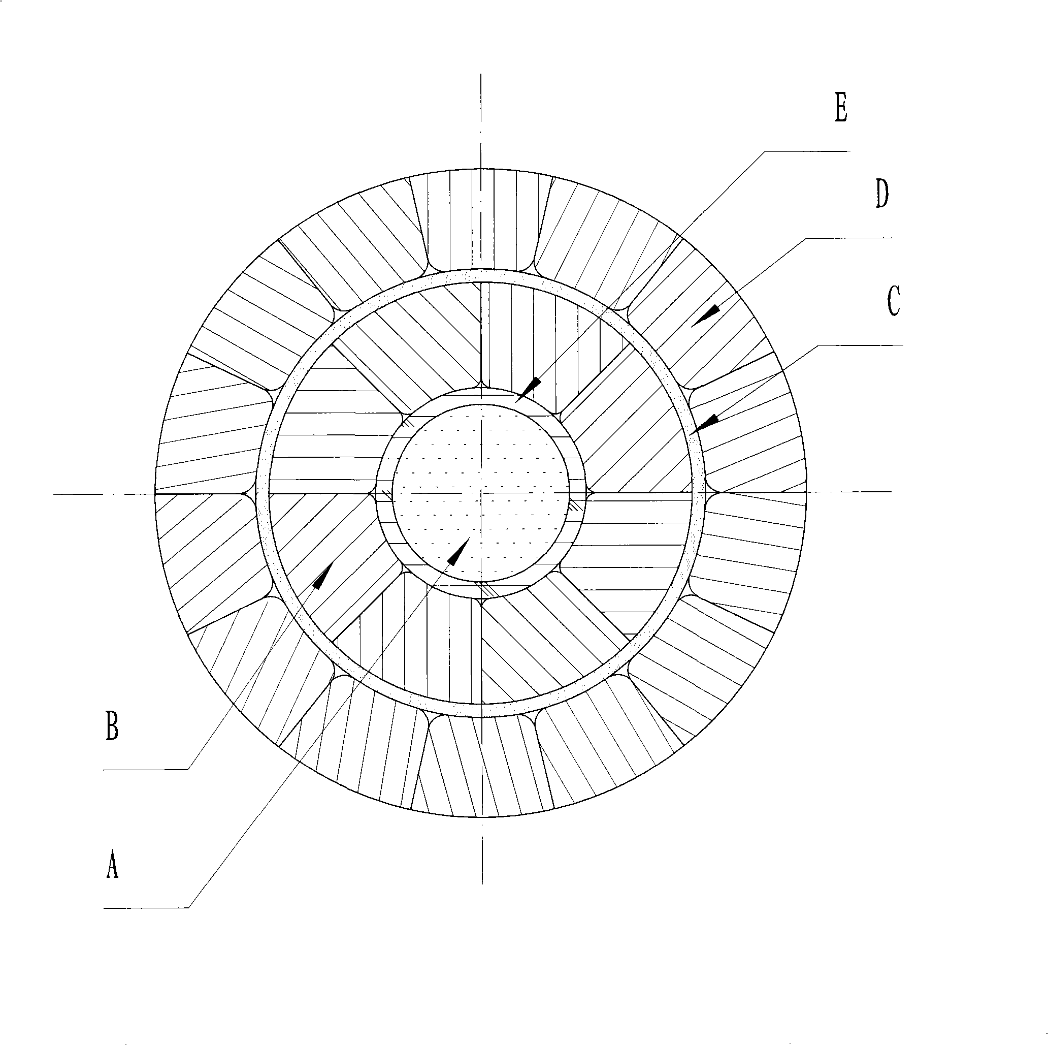
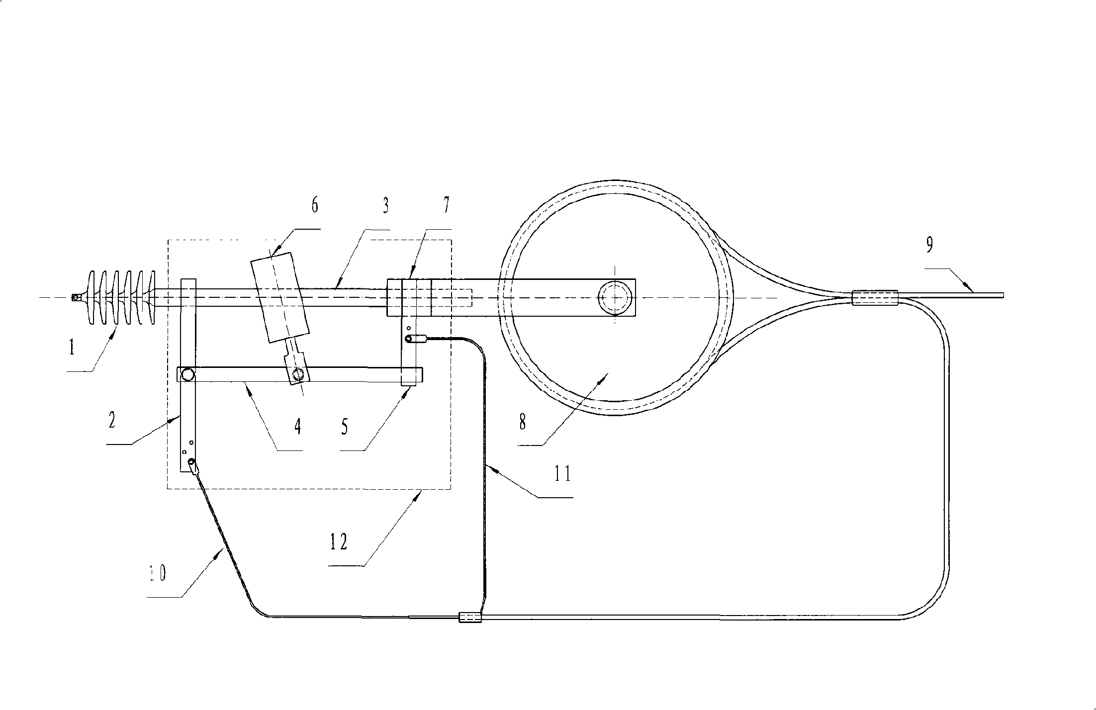
Technical field [0001] The invention relates to a method for realizing on-load ice-melting of the overhead power line by using a layered insulation overhead power line and a changeover switch installed on the insulator string. It belongs to the technical field of high-voltage power transmission. Background technique [0002] The ice melting of high-voltage transmission lines is generally carried out when the operation is stopped, and only one short-circuit ice melting technology is maturely applied in China. Reliable operation is at risk. Contents of the invention [0003] Aiming at this technical problem, a method is proposed to change the current-carrying cross-sectional area of ​​the power line by switching the switch during operation to increase the line loss and heat the wire to achieve the purpose of melting ice. The key to making this method practical is to melt the ice overhead with load Power lines and toggle switches. Refer to attached drawings 1 and 2 of the ...

Claims


Application Information

Patent Timeline
IPC IPC(8): H02G7/16H01B17/52
Inventor 华旭东
Owner 华旭东
Why Eureka
Try Eureka