Radiator core support

A radiator and core technology, applied in heat exchanger shells, indirect heat exchangers, heat exchange equipment, etc., can solve problems such as reducing the cooling performance of condensers

Inactive Publication Date: 2008-11-05
CALSONIC KANSEI CORP
View PDF1 Cites 2 Cited by
  • Summary
  • Abstract
  • Description
  • Claims
  • Application Information

AI Technical Summary

Problems solved by technology

[0006] In addition, in the conventional radiator core bracket, there may be a problem that the hot air on the engine side is blown back to both sides of the condenser through the above-mentioned gap, reducing the cooling performance of the condenser.

Method used


Image

  • Radiator core support
  • Radiator core support
  • Radiator core support

Examples


Embodiment 1

[0027] First, the overall structure of the radiator core support of this embodiment will be described.

[0028] The radiator core bracket of this embodiment is arranged at the front part of the vehicle body and constitutes a part of the vehicle body.

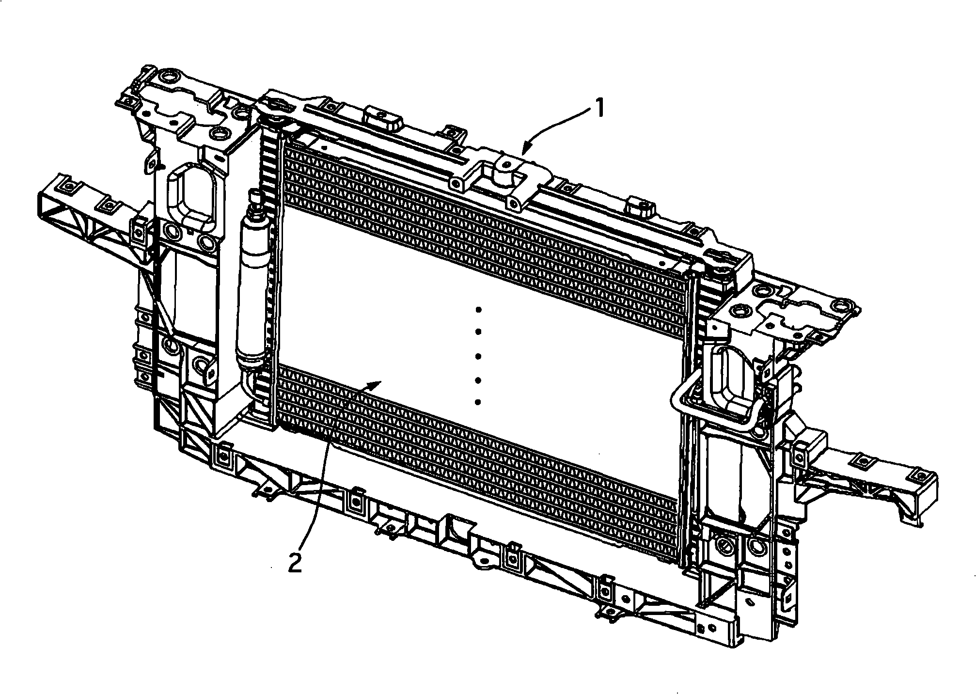
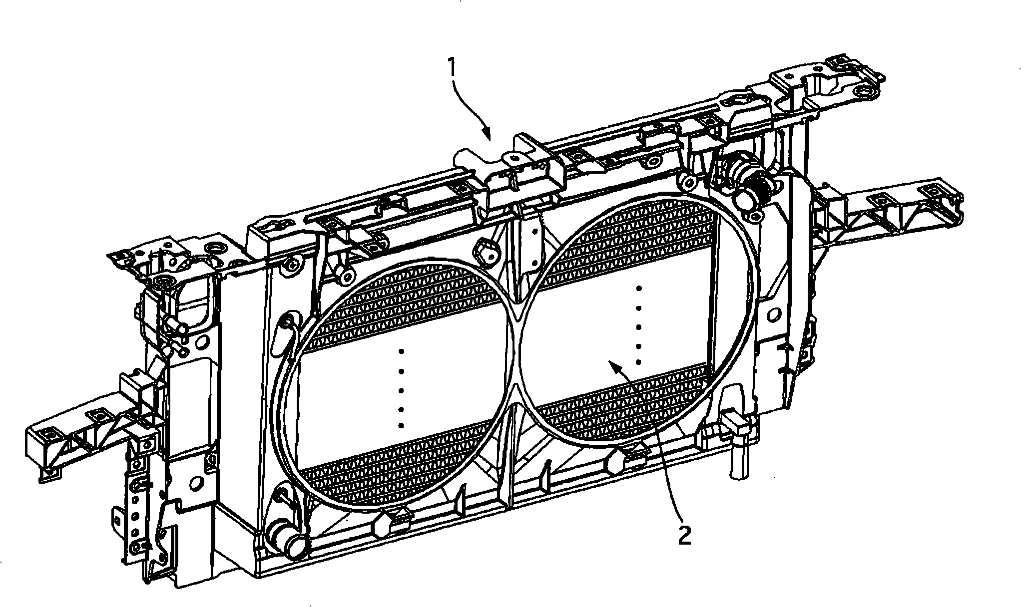
[0029] Such as figure 1 , figure 2 As shown, the radiator core support 1 of this embodiment has an integrated heat exchanger 2 composed of a condenser and a radiator.

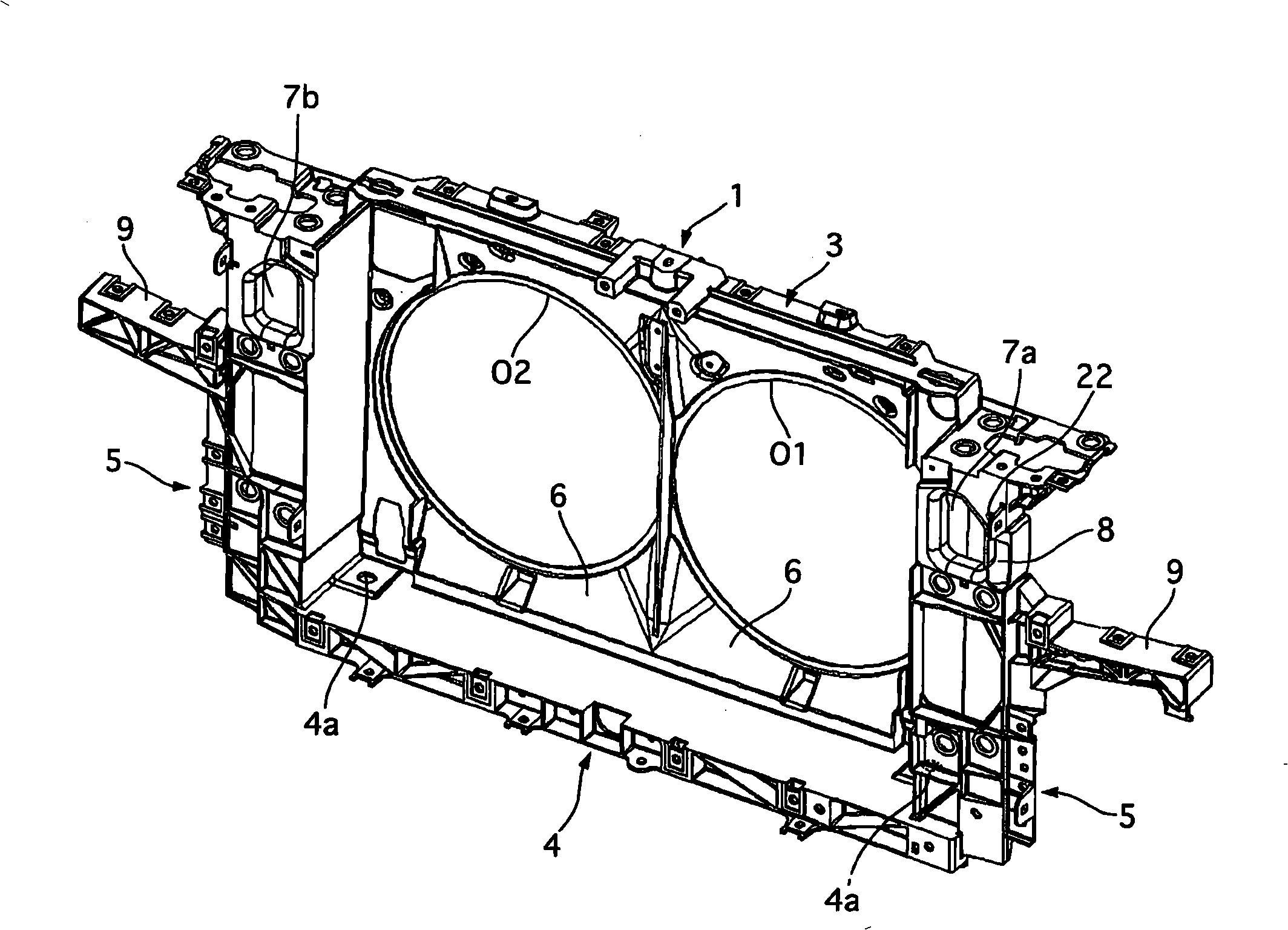
[0030] Such as image 3 , Figure 4 As shown, the radiator core support 1 is composed of a radiator core support upper part 3 extending in the vehicle width direction, a radiator core support lower part 4 arranged in parallel with the radiator core support upper part 3, and a radiator core support lower part 4 arranged in parallel with the radiator core support. The left and right radiator core support side parts 5, 5 that are combined with the two ends of the sub-support upper part 3 and the radiator core support lower part 4, from the above-mentioned radia...


PUM


Abstract

The invention provides a radiator core support. A condenser (10) is placed in front, relative to the vehicle, of a radiator core support (1). Also, connection ends, for connection to the vehicle, of piping (30, 31) of the condenser (10) are placed penetrated through through-holes (8) and projected to the rear side of the vehicle, the through-holes being formed in the radiator core support (1). A bracket (40) is provided at the radiator core support (1), and the bracket (40) is capable of fixedly supporting the piping (30, 31) with gaps between the piping (30, 31) and the through-holes (8) closed.

Description

technical field [0001] The present invention relates to a radiator core support for supporting a radiator of an automobile or the like on a vehicle body. Background technique [0002] Conventionally, Japanese Patent Application Laid-Open No. 2000-18874 discloses a radiator core bracket in which a condenser is arranged on the vehicle front side and a radiator is arranged on the vehicle side rear side. The condenser is arranged in a state where the vehicle-side connection end portion of the condenser pipe penetrates through the through-hole formed in the radiator core bracket and protrudes toward the vehicle rear side. [0003] Patent Document 1: Japanese Patent Laid-Open No. 2000-18874 [0004] However, in the conventional radiator core bracket, since there is a gap between the through hole and the pipe, there is a problem that the pipe is unstable when connecting the vehicle-side connection end of the pipe to the vehicle-side connection pipe, and the pipe is laborious. que...

Claims


Application Information

Patent Timeline
Patent Type & Authority Applications(China)
IPC IPC(8): B60K11/04B60H1/32B60R16/08B62D25/08F25B41/00F28F9/26
CPCF25B39/04F28F9/002B60H1/00571F28D2021/0084B60H1/00535B60K11/04F25B41/00B60H1/32B62D25/08
Inventor 泉水达也上原智明
Owner CALSONIC KANSEI CORP
Why Eureka
Try Eureka