Coil mutual inductance coupling line switch reluctance motor
A switched reluctance motor and mutual inductance coupling technology, applied in the field of switched reluctance linear motors and linear switched reluctance motors, can solve the problems of low motor power density and low winding utilization rate, and achieve full utilization of materials and high power density. Effect
- Summary
- Abstract
- Description
- Claims
- Application Information
AI Technical Summary
Problems solved by technology
Method used
Image

Examples
Embodiment 1
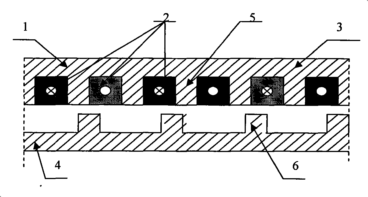
[0011] Example 1, see figure 1 , the present invention consists of a primary 1 and a secondary 4, the primary 1 is composed of a distributed three-phase armature winding 2 and an iron core made of primary laminations 3 made of silicon rigid sheets; the secondary 4 is composed of silicon rigid sheets It is stacked but has no winding; the primary and secondary poles have a salient pole structure, and the primary teeth 5 and secondary teeth 6 are respectively set on the primary 1 and secondary 4; the number of poles on the primary and secondary poles is the same as that of the rotary switch reluctance The motor can be made into 4 / 6, 8 / 12 poles and other forms; the three-phase armature winding of the present invention is a distributed winding, and the mutual inductance between the three-phase windings is coupled with each other, and there are always two phases of excitation at any time during operation.
[0012] This embodiment adopts a unilateral planar linear switched reluctance...
Embodiment 2
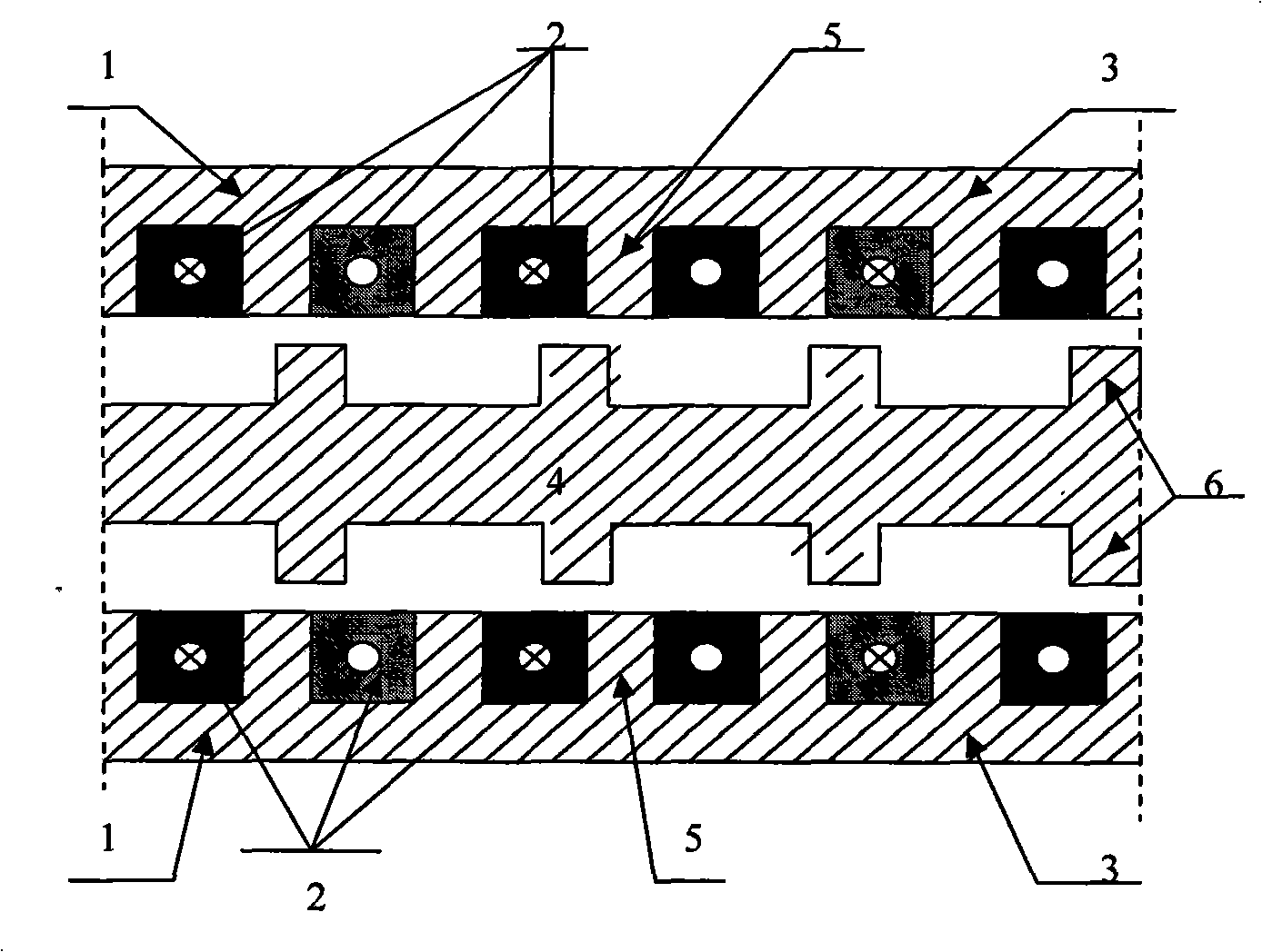
[0013] Example 2, see figure 2 , the present invention can adopt double-sided planar linear switched reluctance motor, including the primary three-phase armature winding, primary pole and secondary pole of mutual inductance coupling. The output force of the motor is increased to a greater extent, thereby further improving the power density of the motor, and at the same time eliminating the influence caused by unilateral magnetic pull.
Embodiment 3
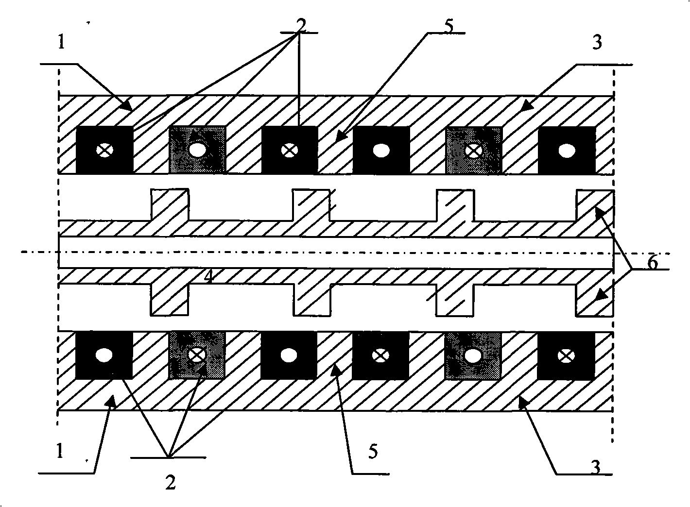
[0014] Example 3, see image 3 , the present invention can adopt a cylindrical linear switched reluctance motor, including primary and primary three-phase armature windings and secondary poles, and other structures are the same as in Embodiment 1.
[0015] The present invention can be made into a moving secondary pole or a moving primary pole. Based on different requirements, it can be a moving coil type or a moving iron core type; it can be operated as a generator or as a motor.
[0016] Working Principle of Mutual Inductance Coupled Linear Switched Reluctance Motor
[0017] combine figure 1 , figure 2 , image 3 , Figure 4 , the principle of mutual inductance coupled linear switched reluctance motor to improve winding utilization and motor power density is as follows.
[0018] The windings of the novel linear switch magnetic group motor proposed by the present invention are distributed windings, such as figure 1 In the winding arrangement shown, the mutual inductance...
PUM
 Abstract
Description
Claims
Application Information
 - Generate Ideas
- Intellectual Property
- Life Sciences
- Materials
- Tech Scout
- Unparalleled Data Quality
- Higher Quality Content
- 60% Fewer Hallucinations
Browse by: Latest US Patents, China's latest patents, Technical Efficacy Thesaurus, Application Domain, Technology Topic, Popular Technical Reports.
© 2025 PatSnap. All rights reserved.Legal|Privacy policy|Modern Slavery Act Transparency Statement|Sitemap|About US| Contact US: help@patsnap.com